6–28
Chapter 6: PLC Communications
6
EA1-MG6-USER-M Hardware User Manual, 1st Ed. Rev C, 09/10
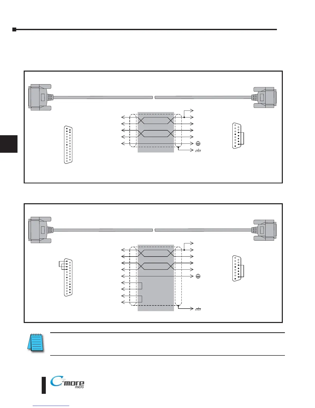
User Constructed Cables – Wiring Diagrams (cont’d)
Diagram 5
Diagram 6
Direct
LOGIC D4-450 Port 3
RS-422A
To PLC
25-Pin Port
25-pin
D-sub
(male)
Wiring Diagram
Note: Use the above wiring diagram to make your own cable. We recommend Belden 8103 shielded cable or equivalent.
1
25
25 = RXD–
(RS422)
24 = RXD+
(RS422)
23 = do not use
22 = do not use
21 = do not use
20 = do not use
19 = do not use
18 = do not use
17 = do not use
16 = do not use
15 = do not use
14 = do not use
13 = TXD–
(RS422)
12 = TXD+
(RS422)
11 = do not use
10 = do not use
9 = do not use
8 = do not use
7 = 0 V
6 = do not use
5 = do not use
4 = do not use
3 = do not use
2 = do not use
1 = do not use
12
13
7
TXD+
TXD–
0V
9
10
5
1
RD+
RD–
shield
RXD+
RXD–
24
25
11
12
SD+
SD–
Term.
13
8 = do not use
7 = do not use
6 = do not use
5 = Logic GND
4 = do not use
3 = do not use
2 = do not use
1 = Frame GND
15 = do not use
14 = do not use
13 = Termination
12 = SD– (RS422)
11 = SD+ (RS422)
10 = RD– (RS422)
9 = RD+ (RS422)
1
15
15-pin
D-sub
(male)
RTS and CTS are not present on this port.
To C-more Micro-Graphic
Serial Port2
Direct
LOGIC D2-DCM*, D3-DCM* & D4-DCM*
RS-422A
To PLC
25-Pin Port
25-pin
D-sub
(male)
Wiring Diagram
Note: Use the above wiring diagram to make your own cable. We recommend Belden 8103 shielded cable or equivalent.
1
25
25 = do not use
24 = do not use
23 = do not use
22 = do not use
21 = do not use
20 = do not use
19 = do not use
18 = do not use
17 = RXD+
(RS422)
16 = RXD–
(RS422)
15 = TXD–
(RS422)
14 = TXD+
(RS422)
13 = CTS–
12 = CTS+
11 = RTS–
10 = RTS+
9 = do not use
8 = do not use
7 = 0 V
6 = do not use
5 = do not use
4 = do not use
3 = do not use
2 = do not use
1 = do not use
14
15
7
TXD+
TXD–
0V
9
10
5
1
RD+
RD–
shield
RXD+
RXD–
17
16
11
12
SD+
SD–
Term.
13
8 = do not use
7 = do not use
6 = do not use
5 = Logic GND
4 = do not use
3 = do not use
2 = do not use
1 = Frame GND
15 = do not use
14 = do not use
13 = Termination
12 = SD– (RS422)
11 = SD+ (RS422)
10 = RD– (RS422)
9 = RD+ (RS422)
1
15
15-pin
D-sub
(male)
11
RTS–
12
CTS+
13
CTS–
10
RTS+
*Note: The DCM modules must be set for:
Direct
NET Slave, HEX mode.
To C-more Micro-Graphic
Serial Port2
NOTE: The RS-422 wiring diagrams shown above are not for multi-drop networks involving connecting more
than one PLC to a panel. Refer to the wiring diagram example on page 6-38 if more than one PLC will be
connected to a panel.
User Constructed
User Constructed