6–33
Chapter 6: PLC Communications
EA1-MG6-USER-M Hardware User Manual, 1st Ed. Rev C, 09/10
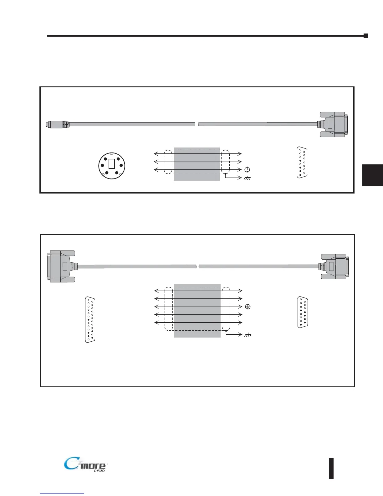
Mitsubishi Q02 / Q02H / Q06H / Q12H / Q25H Serial Driver
and QnA Serial Driver with Direct Connection to
the Serial Port on Q00 and Q01 CPU’s
RS-232C
8 = do not use
7 = do not use
6 = donot use
5 = Logic GND
4 = do not use
3 = RXD (232C)
2 = TXD (232C)
1 = Frame GND
2
15 = do not use
14 = do not use
13 = do not use
12 = do not use
11 = do not use
10 = do not use
9 = do not use
1
15
15-pin
D-sub
(male)
1
3
TXD
RXD
GND
3
2
5
1
RXD
TXD
shield
Wiring Diagram
Note: Use the above wiring diagram to make your own cable. We recommend using 22 AWG shielded cable.
To C-more Micro-Graphic
Serial Port2
To PLC
6-Pin Port
1 = RXD (232C)
2 = TXD (232C)
3 = Logic GND
4 = do not use
5 = do not use
6 = do not use
Mini Din
6-pin Male
1 2
3 4
5 6
Allen Bradley PLC5 DF1
RS-422
8 = do not use
7 = do not use
6 = do not use
5 = Logic GND
4 = do not use
3 = do not use
2 = do not use
1 = Frame GND
To PLC
25-Pin Port
2
15 = do not use
14 = do not use
13 = do not use
12 = SD –
11 = SD +
10 = RD –
9 = RD +
1
15
15-pin
D-sub
(male)
3
7
TXD +
RXD +
GND
10
12
5
1
RD –
SD –
shield
25-pin
D-sub
(male)
Wiring Diagram
Notes:
1. Polarities must be swapped.
2. Handshaking is turned off
3. Use the above wiring diagram if you need to make your own cable. We recommend using 8103 shielded cable or equivalent.
4. Refer to the PLC-5 Programmable Controllers User Manual Switch Setting Reference for details on switch settings to define
the controller's serial port electrical interface.
16
1
25
25 = do not use
24 = do not use
23 = do not use
22 = do not use
21 = do not use
20 = do not use
19 = do not use
18 = do not use
17 = do not use
16 = RXD –
15 = do not use
14 = TXD –
13 = do not use
12 = do not use
11 = do not use
10 = do not use
9 = do not use
8 = do not use
7 = Signal GND
6 = do not use
5 = do not use
4 = do not use
3 = RXD +
2 = TXD +
1 = do not use
To C-more Micro-Graphic
Serial Port2
14
9
11
RD +
SD +
TXD –
RXD –