6–35
Chapter 6: PLC Communications
6
EA1-MG6-USER-M Hardware User Manual, 1st Ed. Rev C, 09/10
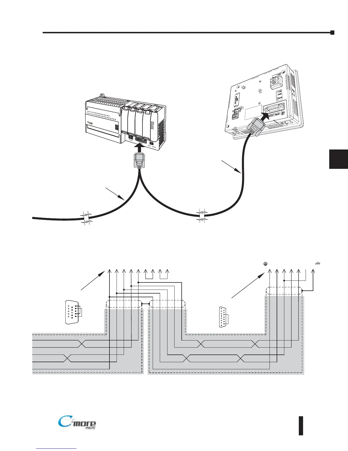
Termination resistors required at both ends of the
network receive data signals to match the impedance
of the cable (between 100 and 500 ohms). Jumper pin
13 to 9 on the C-more 6” Micro-Graphic Serial Port2
15-pin connector to place the 120⏲ internal resistor
into the network. If the cable impedance is different,
then use an external resistor matched to the cable
impedance.
C-more
6” Micro-Graphic
Panel
Port2
8 = do not use
7 = do not use
6 = do not use
5 = Logic GND
4 = do not use
3 = do not use
2 = do not use
1 = Frame GND
15 = do not use
14 = do not use
13 = Termination
12 = SD– (RS422)
11 = SD+ (RS422)
10 = RD– (RS422)
9 = RD+ (RS422)
1
15
15-pin
D-sub
(male)
DirectLOGIC
DL06 PLC
Shielded Cable
shield
shield
5
Term.
SHD
SD–
SD+
RD–
RD+
GND
10 9 12 11 13 1
Typical RS-422 Multi-Drop Wiring Diagram (cont’d)
Signal GND
HD = High Density
15-pin
HD D-sub
(male)
8 = do not use
7 = Sig GND
6 = RXD–
5 = do not use
4 = do not use
3 = do not use
2 = do not use
1 = do not use
15 = CTS–
14 = CTS+
13 = RXD+
12 = RTS-
11 = RTS+
10 = TXD–
9 = TXD+
1
6
15
Shielded Cable
Port 2
To C-more Micro-Graphic
Serial Port2
TXD+
TXD
RXD
RXD+
Note: We recommend Belden 8103 shielded cable or equivalent.
7
RTS+
CTS–
CTS+
RTS–
RXD–
RXD+
TXD–
TXD+
GND
10 9 6 13 11 14 12 15
Signal GND
To DL06 PLC port 2
TXD+
TXD
RXD
RXD+
(Master)
(Slave)
*
*