55
Serviceanleitung / Service Manual / / /
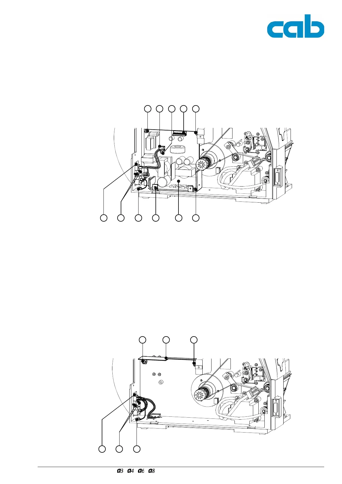
6. Pull the following plugs out of the PCB (12):
- connector (6) from the Power Input Module
- Power Cable (9).
7. Remove three screws (5) and two screws (11) to
remove the power supply (12) and the hind Insulator
Plate.
The Insulator Plate is not any longer needed.
8. Loosen the screw (10) from the grounding cable and
the two screws (9).
6. Ziehen Sie folgende Stecker von der Leiterplatte (12):
- Netzeingang (6)
- Leitung Netzteil (7).
7. Entfernen Sie drei Schrauben (5) und zwei Schrauben
(11) und entnehmen Sie das Netzteil (12) und die
dahinter befindliche Isolierplatte.
Die Isolierplatte wird nicht mehr verwendet.
8. Lösen Sie die Schraube (10) für die Erdungsleitung
und die zwei Schrauben (9).
Bild 35 Montage des Netzteilset 1 I Fig. 35 Mounting the Power Supply Set 1 I
8 11 12109 11
5 756
14 109
5 513
Lieferumfang und Montage des Netzteilset 1
- 5946550Netzteil 1
- 5946551Steckerblech (14)1
- 5946553Abdeckblech incl. Kabelhalter 1
- 5946555Abdeckblech oben (13)1
- 5903011Zahnscheibe DIN6797-A4.3-galZn 1
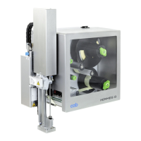
9. Tauschen Sie das Steckerblech (8), Art.-Nr. 5943105,
gegen das Steckerblech (14), Art.-Nr. 5946551, aus
und befestigen Sie es mit zwei Schrauben M4x10 (9).
Befestigen Sie die Erdungsleitung mit der Schraube
M4x6 (10).
10. Montieren Sie das "Abdeckblech oben" (13) mit zwei
Schrauben M4x10 (5) am Gehäuse.
Bild 34 Ausbauen der Original-Netzteilumgebung II Fig. 34 Removing the original Power Supply Section II
Delivery content and mounting Power Supply Set 1
- 5946550Power Supply 1
- 5946551Power Input Module (14)1
- 5946553Cover Plate with Cable Clamps 1
- 5946555Cover Plate (13)1
- 5903011Toothed Washer DIN6797-A4.3-galZn 1
9. Replace the Power Input Module (8), part no. 943105,
by the Power Input Module (14), part no. 5946551,
and fix it with two screws M4x10 (9).
Fix the grounding cable with the screw M4x6 (10).
10. Mount the upper Cover Plate (13) with two screws
M4x10 (5) on the chassis.
5