67
Serviceanleitung / Service Manual / / /
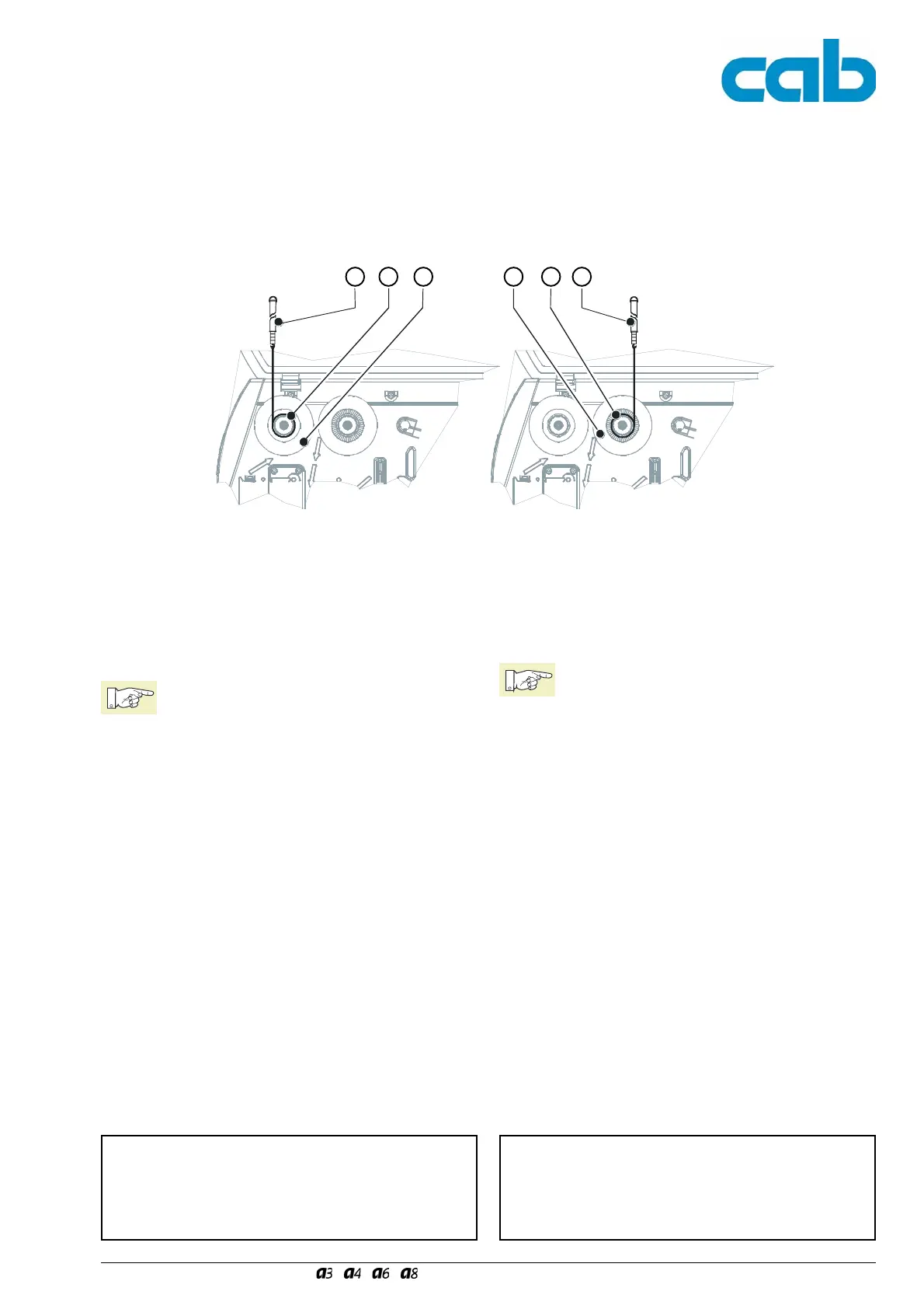
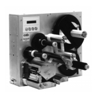
Bild 49 Messung der Momente an den Folienwicklern Fig. 49 Measuring the Torques at the Ribbon Hubs
7. Hängen Sie die Federwaage (1), 10 N, an das
Schnurende und bewegen Sie diese senkrecht nach
oben, bis sich der Wickler zu drehen beginnt.
Um korrekte Werte zu erhalten soll die Schnur
mindestens eine volle Umdrehung vom Prüfkörper
abgewickelt werden!
Hinweis!
Der Zahnriemen zum Antrieb des Transfer-
folienaufwicklers darf sich während der
Messung an diesem Wickler nicht mit-
bewegen. Hierdurch würde der Messwert
verfälscht. Halten Sie den Zahnriemen wäh-
rend der Messung fest.
8. Lesen Sie den Messwert F während des Abwickelns
ab.
7. Attach the spring balance (1), 10 N, to the end of the
string and move it vertically upwards until the hub
starts to rotate.
In order to obtain correct values, the string should be
unwound at least one full turn from the test collar.
Notice!
The toothed belt for driving the transfer ribbon
rewinder must not move during the
measurement at this rewinder. This would
falsify the measured value. Hold the toothed
belt securely during the measurement.
8. During unwinding read the measured value F.
21 43 2 1
Messung am internen Aufwickler
Die Messung der Momente erfolgt über die Bestimmung der
Zugkräfte mit einer auf den Aufwickler aufgewickelten
Schnur. Die Messung erfolgt ohne Prüfkörper!
Der physikalische Zusammenhang zwischen Moment und
Zugkraft lautet:
F = M / r F = Zugkraft
M = Wickelmoment
r = Radius des internen Aufwicklers
(20 mm)
Measuring the Torque at the Internal Rewinder
The torque is measured by determining the traction using a
string which is wound around the rewinder.
Perform the measuring without the test collar!
The physical relation between torque and traction is as
follows:
F = M / r F = traction
M = rewind torque
r = radius of rewind hub
(0.8 in/20 mm)
Sollwerte:
Interner Aufwickler
A3, A4: M
Auf
= 28 - 32 Ncm F
Auf
= 14 - 16 N
A6: M
Auf
= 36 - 44 Ncm F
Auf
= 18 - 22 N
Set values:
Internal rewinder
A3, A4: M
up
= 28 - 32 Ncm F
up
= 14 - 16 N
A6: M
up
= 36 - 44 Ncm F
up
= 18 - 22 N
4. Stecken Sie den Prüfkörper (2) auf den jeweiligen
Wickler (3 oder 4).
5. Klemmen Sie den Prüfkörper mit dem Spreiz-
mechanismus fest (Rändelmutter entgegen dem
Uhrzeigersinn drehen).
6. Wickeln Sie die am Prüfkörper (2) angebrachte
Schnur mehrfach um den Prüfkörper.
4. Attach the test collar (2) to the appropriate hub
(3 or 4).
5. Clamp the test collar with the spreading mechanism
(turn the knurled nut in an anti-clockwise direction).
6. Wind the string attached to the test collar (2) several
times around it.