15
4.1.2 Inserting the Labels into the Print Mechanism
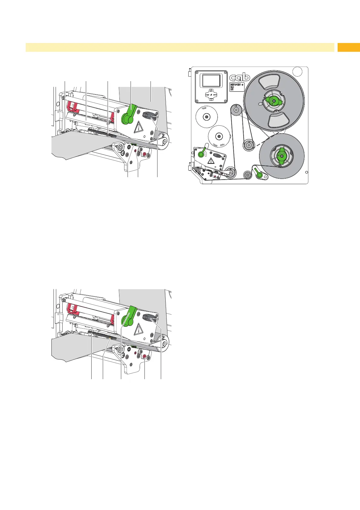
Fig. 10 Inserting the labels into the print mechanism Fig. 11 Label feed path
1. Turn lever (4) counterclockwise to lift the printhead (2).
2. Move the guide (6) to the outermost position by turning the spindle (7) with the Allen key (8).
3. Supply a longer label strip of approx. 100 cm.
4. Guide label strip (5) to the print unit as shown in gure 11. The broken line shows the path for inside wound
labels.
5. Guide label strip through the label sensor (3) to the peel-off edge.
6. Move the guide (6) against the label strip by turning the spindle (7).
7. Forward the label strip over the peel-off edge (1), that the strip reaches back internal rewinder. Remove the labels
from the overhanging strip.
4.1.3 Setting the Label Sensor
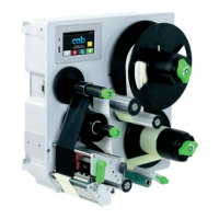
Fig. 12 Setting the Label Sensor
The label sensor (1) can be shifted perpendicular to the direction of paper ow for adaptation to the label medium.
The sensor unit of the label sensor is visible from the front through the print unit. When the printer is switched on, a
yellow LED illuminates the sensor position (2).
Position label sensor by turning the spindle (4) with the Allen key (5) in such a way that the sensor can detect the
label gap or a reex or cut-out mark.
- or, if the labels deviate from a rectangular shape, -
Align label sensor with the front edge of the label in the direction of paper ow.
Turn lever (3) clockwise to lock the printhead.
4 Loading Material