Electronic Instrumentation
UM3148 – DT5730/DT5725 User Manual rev. 2
Event Structure
The event can be readout via Optical Link or USB; data format is 32-bit long word (see Tab. 9.3)
An event is structured in:
• Header (four 32-bit words)
• Data (variable size and format)
Header consists in 4 words including the following information:
• EVENT SIZE (Bit[27:0] of 1
st
header word) = It is the size of the event (number of 32-bit long words);
• BOARD FAIL FLAG (Bit[26] of 2
nd
header word) = Implemented from ROC FPGA firmware revision 4.5 on
(reserved otherwise), this bit is set to “1” in consequence of a hardware problem (e.g. PLL unlocking or over-
temperature condition). The user can collect more information about the cause by reading at register address
0x8104 and contact CAEN Support Service if necessary (see § 14);
• Bit[24] (2
nd
header word) = This bit identifies the event format; it is reserved and must be 0;
• Bit[23:8] (2
nd
header word) = Starting from revision 4.6 of the ROC FPGA firmware, these 16 bits can be
programmed to provide different trigger information according to the setting of the bits[22:21] at register
address 0x811C (Tab. 9.2).
Note: for ROC FPGA firmware revisions lower than 4.6. these bits are reserved.
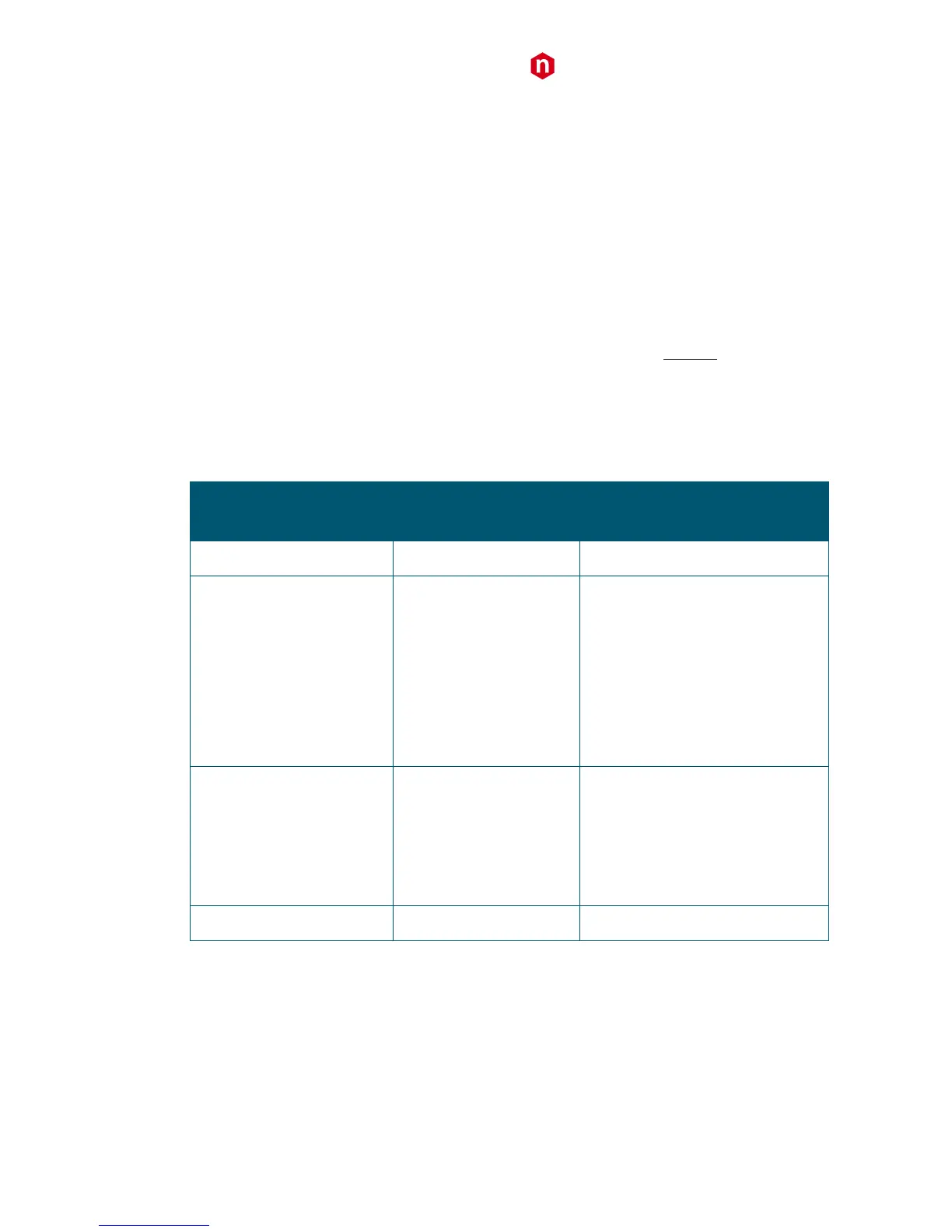
REGISTER 0x811C
Bits[22:21]
Bit[23:8]
(16 bits in the2
nd
header word)
Indicates the trigger source causing the
event acquisition:
Bits[23:19] = 0000
Bit[18] = Software Trigger
Bit[17] = External Trigger
Bit[16] = 0
Bits[11:8] = Trigger requests from the
couple of channels (refer to § Self-Trigger)
Extended Trigger Time Tag
(ETTT)
A 48-bit Trigger Time Tag (ETTT)
information is configured, where Bits[23:8]
contributes as the 16 most significant bits
together to the 32-bit TTT field (4
th
header
word).
Note: in the 48-bit TTT, the overflow bit is
not provided.
Tab. 9.2: TRG OPTIONS configuration table
• CHANNEL MASK (Bit[7:0] of 2
nd
header word) = It is the mask of the channels participating in the event. This
information must be used by the software to acknowledge which channel the samples are coming from.
• EVENT COUNTER (Bit[23:0] of 3
rd
header word) = This is the trigger counter; it can count either accepted
triggers only, or all triggers.


 To Next Page