General information
10
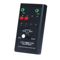
To the user, the 1902 comprises two completely separate
functional blocks: the waveform signal conditioner and the
trigger generator.
The waveform conditioner provides one channel of output, with
the input selected via software from a range of input
connections. There is a comprehensive set of conditioning
controls: gain selection, filtering and offsetting, and overrange
detection. The 1902 may readily be adapted to different
specialized signal sources, requiring additional control (for
instance clamping), by a choice of internal daughterboards. The
computer can read back the characteristics of these daughter-
boards.
By default, digital filtering is installed in your 1902 (the
alternative being analogue filter sections on a daughterboard).
The digital filter processing section is based on a 16-bit ADC
carrying out conversions at 30 kHz; this interrupts the
microprocessor, which carries out digital processing as required
before writing the modified data to the DAC, which is also
clocked at 30 kHz. The digital processing imposes a time delay
(latency) of approximately 0.35 ms on the data at the time of
recording. During playback, Spike2 or Signal can be configured
to remove this delay if required.
2-pole or 3-pole digital filters can be applied, with either Bessel
or Butterworth response. The corner frequencies are selected
from dropdown lists, or users may type in their own values:
high-pass from 0.01 to 1000 Hz, low-pass from 1 to 10,000 Hz.
There is a rectification option, useful for EMG studies. The
digital filtering system can also be used to output ADC data
down the serial line at up to 100 Hz.
The trigger generator provides one output channel of pulses,
derived from a choice of two inputs selected by program. It
uses comparator circuitry with hysteresis to generate clean TTL
pulses from a variety of trigger input sources.
The Trigger2 input can be used to trigger the EEG input-
clamping circuit, if this option has been fitted (see page 41).
1902 functional
organization