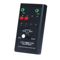
Electrical specification
30
The trigger circuit accepts signals from high-impedance sources
that cannot drive TTL inputs, such as sensors; it can also be
wired to a switch. Trigger connections are made to two mini-
DIN sockets on the front panel, one of which will always be
active, as shown by its yellow
Gate LED. Each trigger input
drives a comparator, which responds to a positive-going signal
(by default), giving a flash on its yellow
Trig LED. In
1902 Mk IV, the comparator may be set to trigger on a
negative-going signal. The comparator has hysteresis: it fires on
a rising voltage at 1.5 V, but does not relax until it has fallen
back to 1.0 V. This reduces repeated triggering from noisy
signals. The trigger circuit output is through a standard BNC
socket. The driver is a 74HCT04 inverter element; this chip is
in a socket, for easy replacement in case of damage.
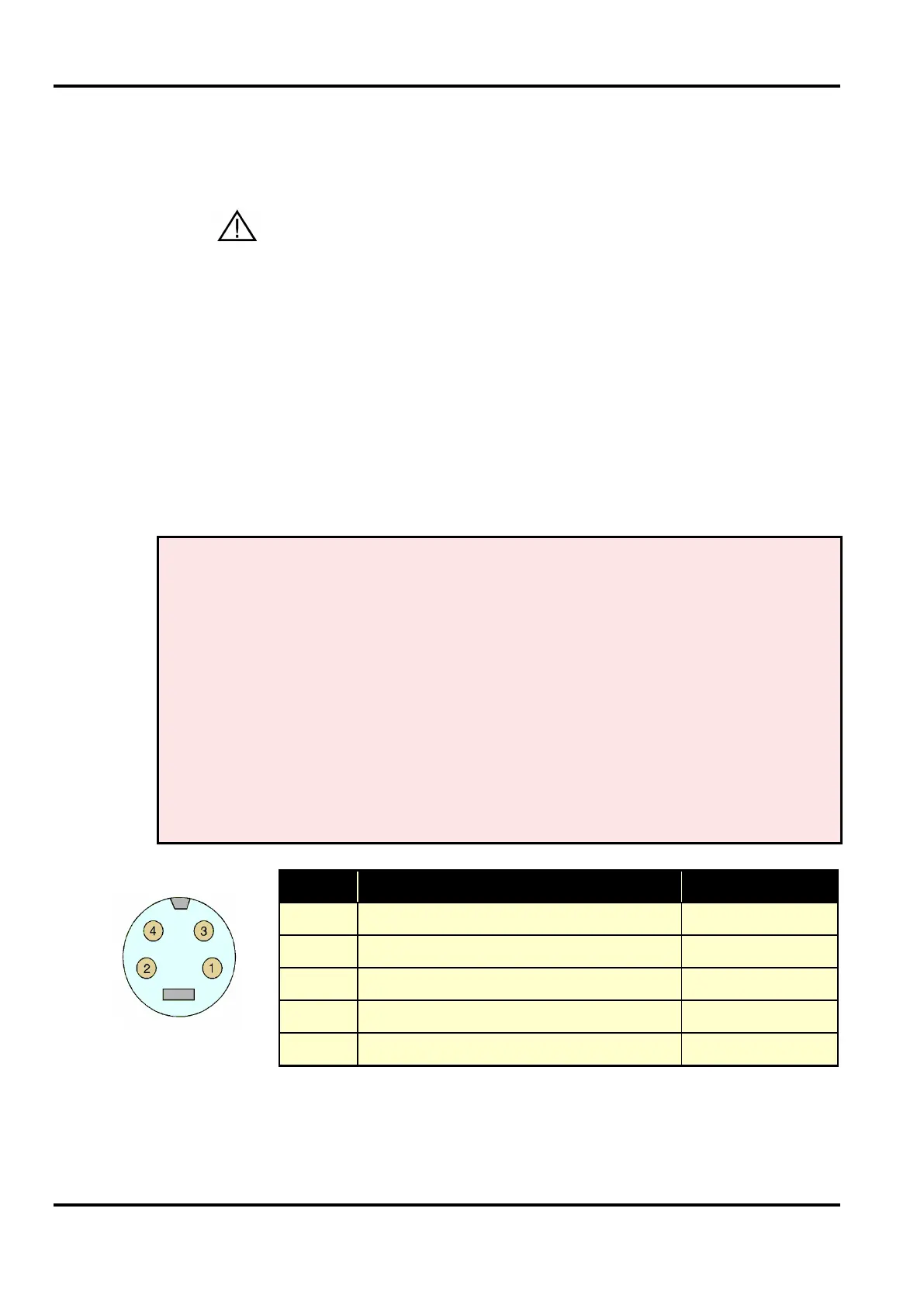
Trigger input voltage range, operating ±15 V
no damage ±50 V
Input impedance 100 kOhm
Trigger threshold for +ve going input +1.5 V approx.
Lower trigger threshold +1.0 V approx.
Output pulse TTL negative-going
Output pulse length 3 µs nominal
Trigger output drive capability 0.8 mA maximum
1 Comparator input
2 Trigger ground
3 Internal pull-up: 5V via 4K7
4 Internal pull-down: 0V via 4K7
Shell Mains earth
• A human subject must NOT be connected to this input
socket
Trigger input
4-pin mini-DIN