Application software
22
This toggles between the two trigger inputs, which are
functionally identical. A check box can set triggering to occur
on the falling edge. (In previous versions of the 1902 only the
rising edge could be used.) Unchecking Trigger 1 sets
Trigger 2; one must always be selected. Note that the clamp
option (see page 41) always uses Trigger 2; when the clamp
option is in use, Trigger 1 may be used as an independent
trigger channel.
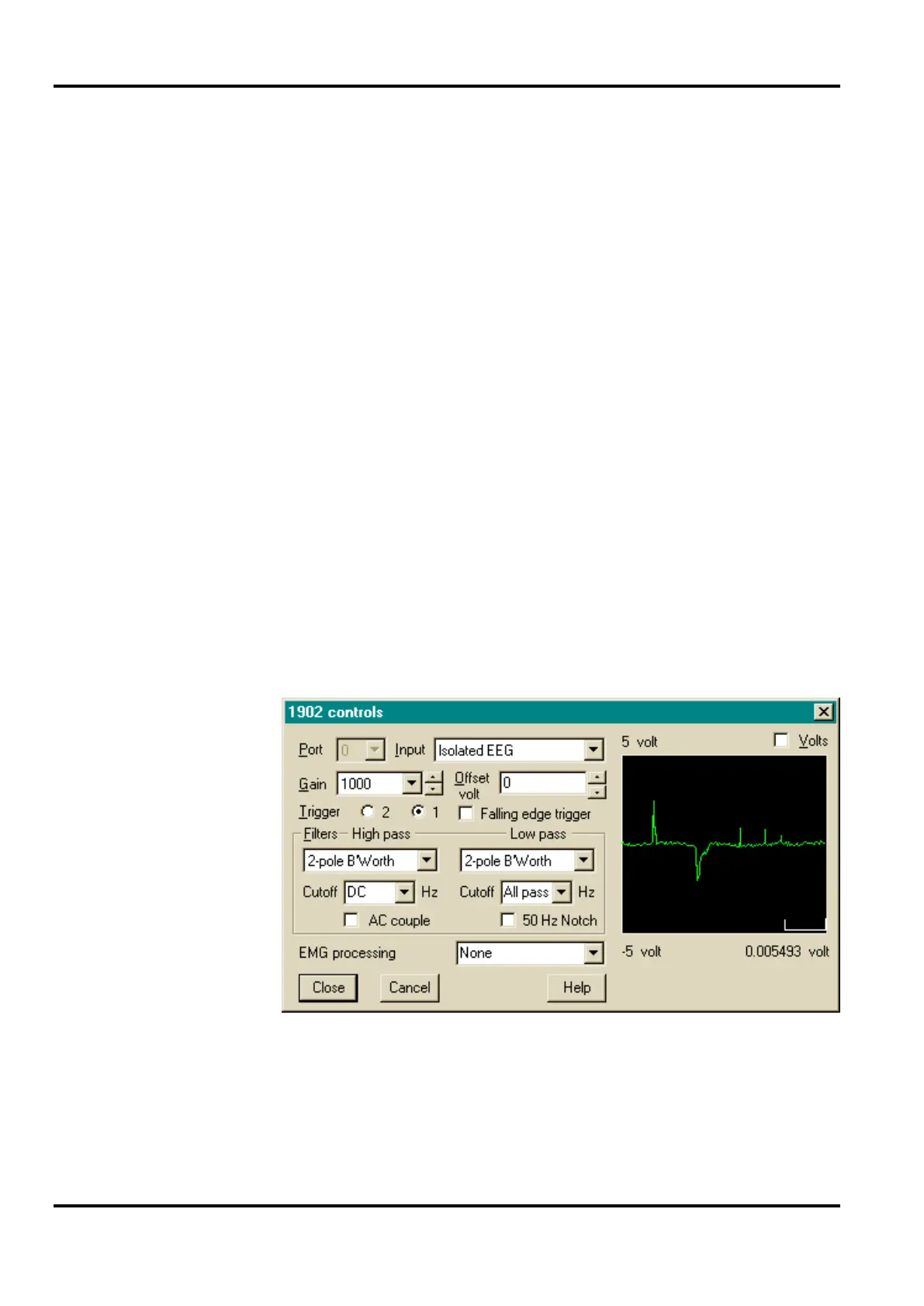
Most users will run the 1902 as a hardware adjunct to a CED
1401 interface, operating under one of CED’s principal
software packages, Spike2 or Signal. CED applications control
the 1902 hardware through an applet similar to the Stand-alone
Control Panel. This appears either with or without an
oscilloscope-style display on the right. The version with the
display appears during the setup phase; the display assists the
user in adjusting gain, filtering, offset, etc. It is not a true
oscilloscope, of course, but a digitized simulation using data
from the 1401’s ADC (analogue to digital converter) sampling
the appropriate input channel.
Control of 1902 setup from CED application
During sampling, the oscilloscope display is not available.
Access to the ADC cannot be guaranteed; quite likely it will be
too busy doing other things! Also, the display generated by the
application itself (see examples below) usually renders the
oscilloscope superfluous.
panel with CED