Details of operation
39
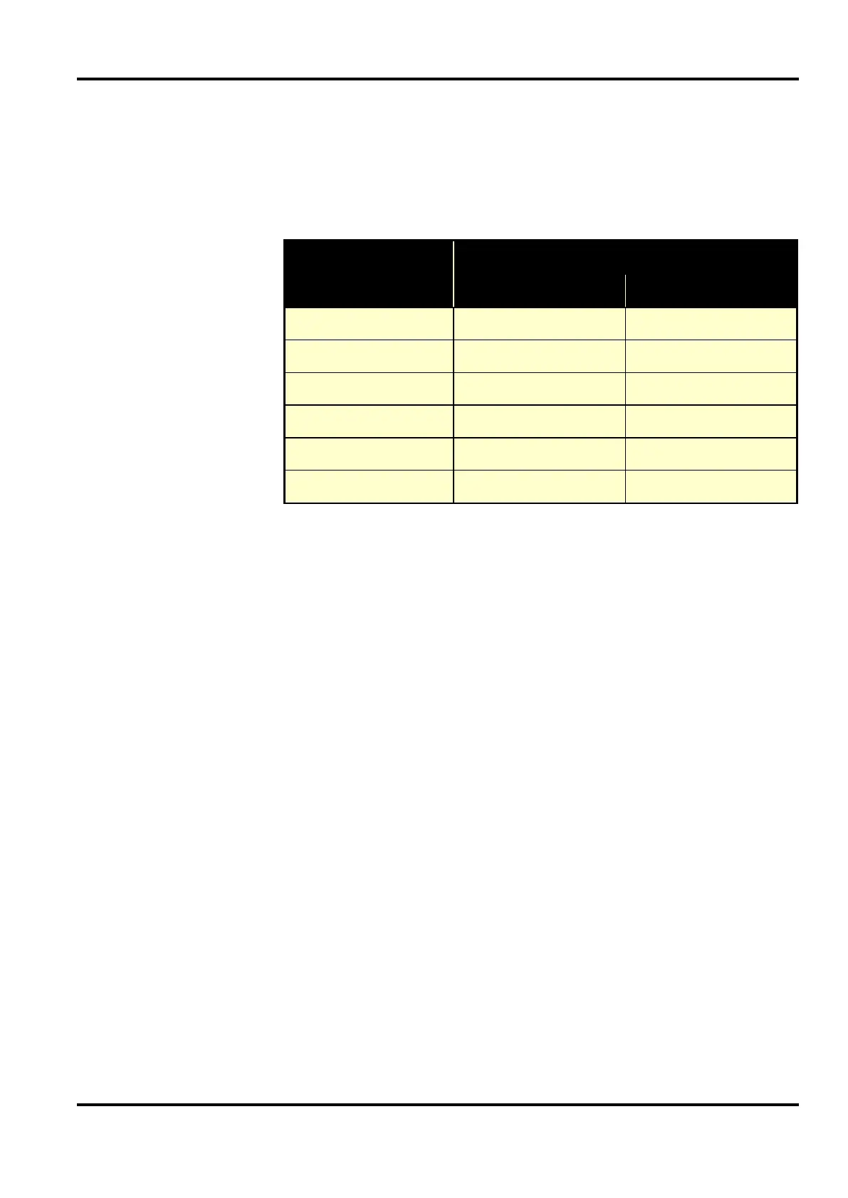
The table shows the calculated degradation of CMRR with
input loading. It can be seen that the buffer circuit has clear
advantages in multi-channel configurations.
Number of inputs
CMRR @ 50Hz (dB)
With buffer
1 >120 >120
2 91 96
3 85 96
4 79 96
6 67 96
8 55 96
There are several possible problems associated with the use of a
buffer circuit:
1. The buffer introduces additional noise. The amplifier used in
the 1902 buffer option is the same type as is used in the main
inputs, so the resulting noise voltage is not more than
√2 times that of an unbuffered configuration.
2. The buffer has to be exactly unity gain if the common-mode
rejection performance is to be maintained. The standard
circuit using an operational amplifier as a buffer falls short of
unity gain by an amount proportional to the reciprocal of the
open-loop gain of the amplifier at the frequency being
considered. The 1902 uses a more sophisticated circuit that is
adjusted to exactly unity gain at (say) 50 Hz.
3. A buffer introduces some phase shift in the signal passing
through it. This can reduce the common-mode rejection of
the multiple-channel system, but the resulting performance is
independent of the number of channels connected to the
buffer output (see table above.)
For wiring the buffer in, see the isolated input connector pinout
table on page 27. CED Electrode Boxes (CED1902-11-2B and
CED1902-11-4B) make the buffer input and outputs available
as touch-proof terminals.
Advantages of
using a buffer
Drawbacks of
using a buffer