EasyManuals Logo

CAME BK Series Installation Manual

CAME BK Series
28 pages
To Next Page IconTo Next Page
To Previous Page IconTo Previous Page
Page #6 background imageLoading...
Page #6 background image
p. 6 - Manual FA01292-EN - 12/2018 - © CAME S.p.A. - The contents of this manual may change, at any time, and without notice. - Original instructions
STANDARD INSTALLATION
1. Operator
2. Limit-switch fins
3. Rack
4. Key-switch selector
5. Antenna
6. Flashing light
7. Photocells
8. Small post
9. Mechanical gate stop
10. Sensitive safety-edge
11. Junction pit
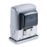
DESCRIPTION OF PARTS
1. Cover
2. Front cover
3. Gear motor
4. Fan
5. Condenser
6. Mechanical limit switch
7. Anchoring plate
8. Control board rack
9. Control board
10. Limit-switch fins
11. Transformer
12. Mounting braces for housing accessories (optional)
13. Release hatch
14. Fastening hardware

Other manuals for CAME BK Series

Questions and Answers:

Question and Answer IconNeed help?

Do you have a question about the CAME BK Series and is the answer not in the manual?

CAME BK Series Specifications

General IconGeneral
Motor Voltage230 V AC
Operating Temperature-20°C to +55°C
Power Supply230V AC
Motor Power300W
Limit Switch TypeMechanical
Safety FeaturesObstacle detection

Related product manuals