300
500
450
p. 7 - Manual FA01292-EN - 12/2018 - © CAME S.p.A. - The contents of this manual may change, at any time, and without notice. - Original instructions
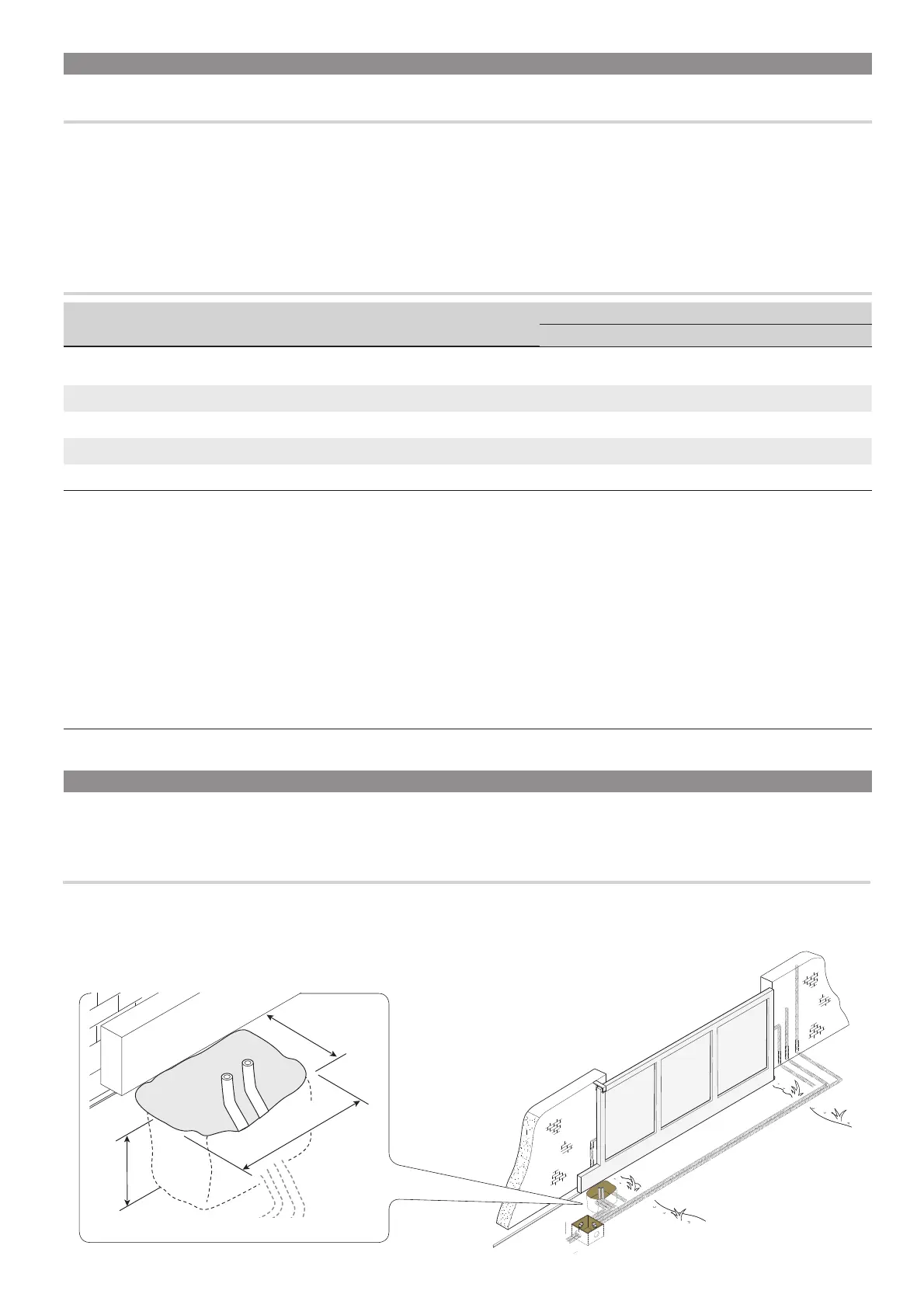
LAYING THE CORRUGATED TUBES
Dig a hole for the foundation frame.
Set up the corrugated tubes needed for the wiring coming out of the junction pit.
For connecting the gearmotor we suggest using a Ø 40 mm corrugated tube, whereas for the accessories we suggest Ø 25 mm tubes.
The number of tubes depends on the type of system and the accessories you are going to fi t.
GENERAL INSTALLATION INDICATIONS
⚠
Only skilled, qualified staff must install this product.
PRELIMINARY CHECKS
⚠
Before beginning the installation, do the following:
• check that the upper slide-guides are friction-free;
• check that the gate is stable and that the casters are in good working order and lubricated;
• check that the ground rails are well-fastened, entirely on the surface and are smooth and level so as not to obstruct the gate's movement;
• make sure you have fitted opening and closing mechanical gate stops;
• make sure that the point where theoperator is fastened is protected from any impacts and that the surface is solid enough;
• set up suitable tubes and conduits for the electric cables to pass through, making sure they are protected from any mechanical damage.
CABLE TYPES AND MINIMUM THICKNESSES
Connection
cable length
< 20 m 20 < 30 m
Input voltage for 230 V AC control board
(1P+N+PE)
3G x 1.5 mm
2
3G x 2.5 mm
2
Flashing light
2 x 0.5 mm
2
Command and control devices
2 x 0.5 mm
2
TX Photocells
2 x 0.5 mm
2
RX photocells
4 x 0.5 mm
2
When operating at 230 V and outdoors, use H05RN-F-type cables that are 60245 IEC 57 (IEC) compliant; whereas indoors, use H05VV-F-
type cables that are 60227 IEC 53 (IEC) compliant. For power supplies up to 48 V, you can use FROR 20-22 II-type cables that comply with EN
50267-2-1 (CEI).
To connect the antenna, use the RG58 (we suggest up to 5 m).
For combined connection and CRP, use a UTP CAT5-type cable (up to 1,000 m long).
If cable lengths differ from those specified in the table, establish the cable sections depending on the actual power draw of the connected
devices and according to the provisions of regulation CEI EN 60204-1.
For multiple, sequential loads along the same line, the dimensions on the table need to be recalculated according to the actual power draw
and distances. For connecting products that are not contemplated in this manual, see the literature accompanying said products
INSTALLING
⚠
The following illustrations are mere examples in that the space for fastening the operator and accessories varies depending on the installation area.
It is up to the fi tter, therefore, to choose the most suitable solution.
The drawing show an operator fitted on the left.

 Loading...