230V0
0
17 25
10 11 E 5
24 0
+ -
p.
11 - Manual code:
FA00095-EN v.
4 - 08/2017 - © Came S.p.A. The contents of this manual may be changed at any time without prior notice.
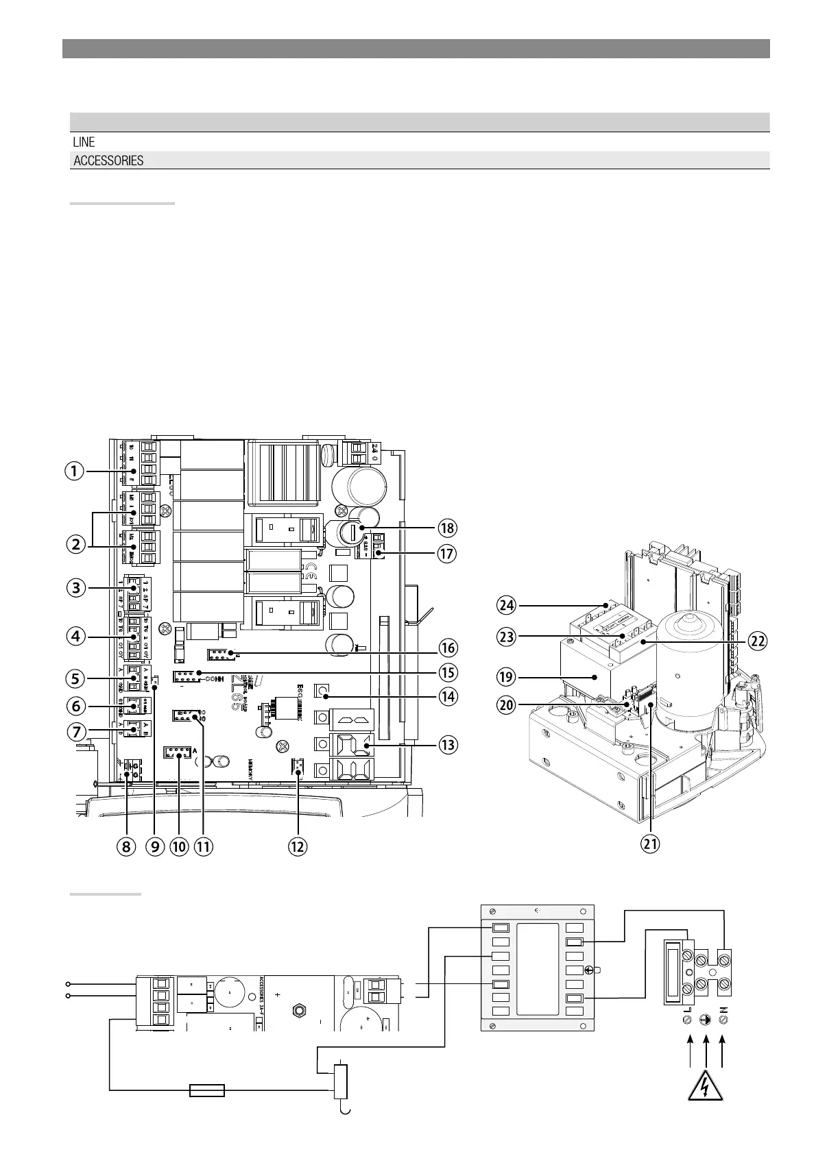
Description of parts
1. Terminals for signaling devices
2. Gearmotors with encoder terminals
3. Control devices terminals
4. Safety devices terminals
5. CRP connection terminals
6. Keypad selector terminal
7. Terminals for transponder devices
8. Antenna terminal
9. Module connector CONNECT GW
10. AF card connector
11. R700/R800 board connector
12. Memory Roll card connector
13. Display
14. Programming buttons
15. Connector for the RIO-CONN card
16. RSE board connector
17. Terminals for the RGP1 module
18. Accessories fuse
19. Transformer
20. Power supply terminal board
21. Line fuse
22. Housing for the CONNECT GW module
23. Housing for the RGP1 module
24. Housing for the RLB card
ELECTRICAL CONNECTIONS AND PROGRAMMING
⚠
Warning! Before working on the control panel, cut off the main current supply and, if present, remove any batteries.
All connections are quick-fuse protected.
FUSES ZL65
- Line 2 A-F = 230 V
- Accessories
2 A-F
230 V AC - 50/60 Hz
Accessories power supply
output 24 V AC/DC, max 20 W
24 V AC/DC control board
power-supply input
Electrolock connector rated for 12 V AC - max 15 W.
Connect a fuse (not supplied) and select 2 from
function F 10.
Power supply
Transformer

 Loading...