3.3 F
LANGE FOCAL D
ISTANCE ADJUSTMENT
<PURPOSE>
• To adjust the flange focal distance (mount standard surface - outer rail surface) to
44.14 mm.
<STANDARD>
• Flange focal distance: 44.14 ± 0.04mm (Measured with the parallel glass
used for the outer rail)
• Parallelism: 0.05 mm or less (against the glass surface)
• Pressure plate center value: 44.17 ± 0.04mm (Pressure plate’s center
measured)
* The pressure plate center value data is used for the AF basic adjustment during
electrical adjustments.
• Tunnel amount: 0.21 ± 0.02mm (Difference between inner and
outer rails)
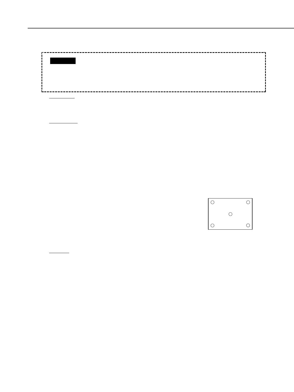
• Pressure plate’s center depression: 0.030 ± 0.020mm (Based on outer rail)
* The pressure plate’s center depression is represented by
E in the figure on the right.
* Within the aperture in the left figure, E must be a
depression among the five points.
Compared to E, one of the A, B, C, and D points must
be +15 um or less and one other point must be +5 um
or less, and the remaining two points must be a
negative amount.
<TOOLS>
• Dial gauge, reinforcement ring (2mm)
• Optical flat
• Flange focal distance gauge (44.14 mm or 42.14 mm), parallel glass
* To measure the flange focal distance with high precision, use a dial gauge (CY9-
7094) that can measure in 0.001mm increments.
Part 3: Repair Information
3-39
• Do this adjustment after replacing the front panel unit, mount, or body
unit.
• Before measuring the flange focal distance, use a parallel glass to check
that there are no gross distortions on the rail surface.
• After the adjustment, be sure to check the viewfinder focus.
CAUTION


 To Next Page