System Setup
Line Title
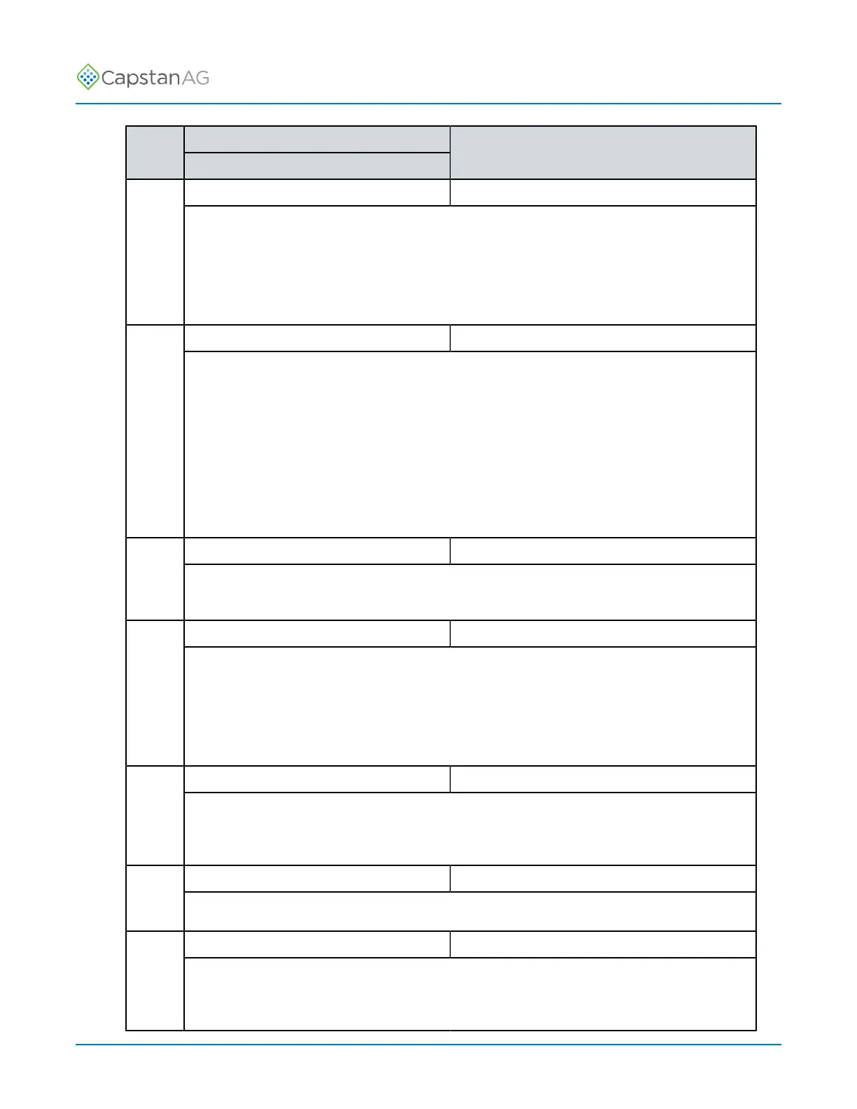
Line
Number
Description
Action
Gain - Differential Press ENTER to change.9
The differential gain causes the control system to accumulate errors faster when errors
are small. The higher the number, the more sensitive the control system. To stabilize an
oscillating system, use a lower number. To speed up a sluggish system, use a higher
number. Differential gain is rarely used and is generally set at 1/10th of the integral gain or
zero.
Total Number Valve Expected Press ENTER to change.10
The total number of valve expected value is the number of valves on the sprayer. At
system power on, the system counts the number of valves reported by the VCMs. If the
reported number matches the manually entered number for the value, then all is OK, and
the system continues. If an error is detected, then an alarm is sounded and diagnostic
readouts show. The system cannot detect valve issues that may have occurred when the
system was not running. If the valve was damaged, or corrosion sets in over the winter,
this is the error you will get. The system cannot determine which nozzle is affected if the
problem occurred when the system was powered off, so use the CapView location setup
screen and look for a nozzle that is not connected.
Scrolling Enable/Disable Press ENTER to change.11
In the nozzle diagnostics on the operation screen, scroll from nozzle to nozzle. To focus on
a single nozzle without the scrolling taking place, select disabled here.
GPS - Ant. Ahead of Rear Axle Press ENTER to change.12
Enter the number of inches from the rear axle to the GPS antenna. A positive number
indicates that the antenna is ahead of the axle. A negative number indicates that the
antenna is behind the axle. This value is used for the GPS overlap control to shut off the
nozzles in the proper place. The GPS antenna must be located on the vehicle on which
the boom is mounted. For pull-behind units, mount the GPS antenna on the implement.
GPS - Ant. Right of Center Press ENTER to change.13
Enter the number of inches that the GPS antenna is off-center. A positive number
indicates that the antenna is right of center. A negative number indicates that the antenna
is left of center.
GPS Antenna Above Ground Press ENTER to change.14
Enter the number of inches that the GPS antenna is above ground.
GPS Boom Ahead of Rear Axle Press ENTER to change.15
Enter the number of inches that the boom is from the rear axle. A positive number
indicates that the boom is ahead of the rear axle. A negative number indicates that the
boom is behind the rear axle.
©
2020 Capstan Ag Systems, Inc. 46 PinPoint
™
II