8200-M035-O1 Rev C 200 Installation & Technical
INSTALLATION, CONT.
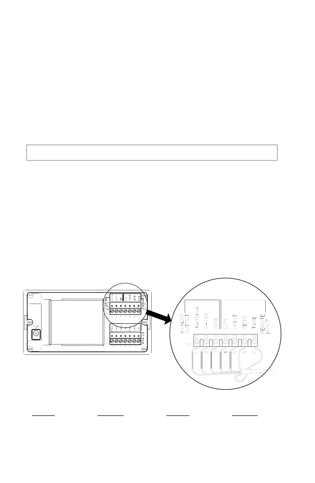
Optically Isolated Remote Inputs
Included with the I/O are 4 programmable inputs that may be used to remotely (up to 100 feet)
initiate various functions within the indicator. These inputs are accessed via a terminal block
(P2) on the rear panel of the indicator. See Figure No. 8.
1. The REMOTE INPUT wires are connected to the P2 terminal block on the rear panel of the
indicator. Refer to Figure No. 8 for the location of P2.
2. Remove 2" of the outer insulation jacket then remove 1/4" of insulation from each wire.
3. Connect each of the wires to terminal block P2 referring to the labels on the rear panel and
the P2 detail view for terminal connections.
4. Loosen the screws in the terminal block, then slip the wire into the terminal opening and
tighten the screw to lock the wire in place. Repeat the procedure until all wires are in place.
NOTE: Remember that the input must be momentarily connected to one of the
GND terminals on P3 to initiate the function.
Optional Analog Output (200-A Only)
The optional Analog Output Option DAC (Digital to Analog Converter) board consists of both a
0 to 10 volt and 4 to 20 mA analog output. Refer to the 2XX-DAC Digital to analog Converter
Analog Output manual (8200-M350-O1) for installation and setup of the DAC board.
1. The ANALOG OUTPUT wires are connected to the P2 terminal block on the rear panel of
the indicator. Refer to Figure No. 8 for the location of P2.
2. Remove 2" of the outer insulation jacket then remove 1/4" of insulation from each wire.
3. Connect each of the wires to terminal block P2 referring to the labels on the rear panel and
the P2 detail view for terminal connections.
4. Loosen the screws in the terminal block, then slip the wire into the terminal opening and
tighten the screw to lock the wire in place. Repeat the procedure until all wires are in place.
ANALOG OUTPUT (200-A Only) REMOTE INPUT