8200-M035-O1 Rev C 200 Installation & Technical
INSTALLATION, CONT.
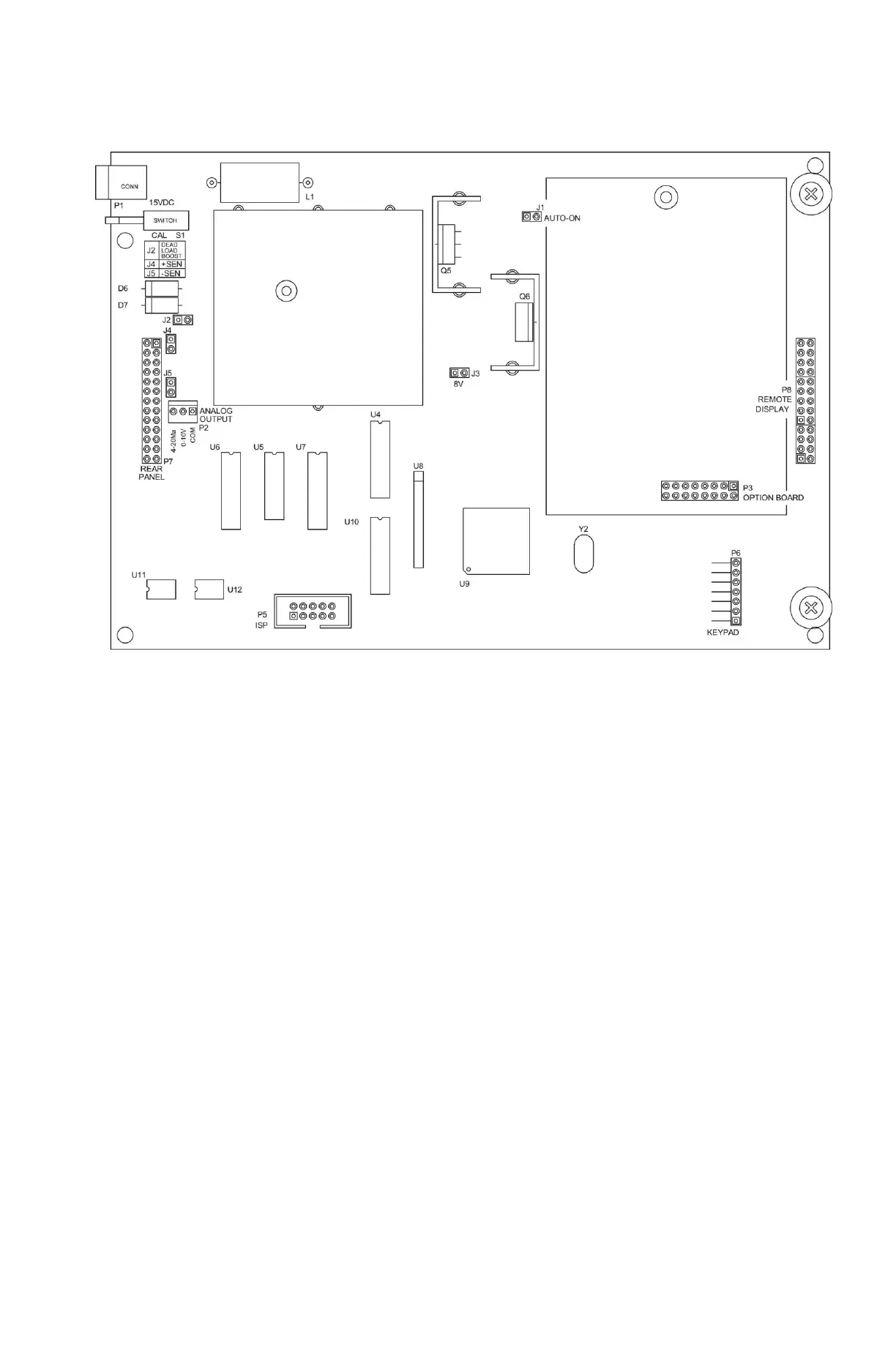
Main PCB
Figure No. 9
Main PCB Jumpers
J1 - AUTO-ON JUMPER
The AUTO-ON jumper J1, when connected, will cause the indicator to power on automatically
whenever power is applied to the power input connector. If power is lost momentarily and then
reapplied, the indicator will turn on without pressing the ON key.
J2 - DEAD LOAD BOOST JUMPER
For very low dead loads (less than 10% of the combined load cell capacity) connect the dead
load boost jumper J2 on the printed circuit board.
J3 - 8V EXCITATION JUMPER
The 8V EXCITATION jumper J3, when connected, sets the load cell excitation voltage to 8V
for operation with a 12 VDC battery. To operate from a 12 VDC battery, the load cell excitation
voltage MUST be set to 8 VDC (J3 closed). Battery operation with the load cell excitation
voltage set to 12V will result in an unstable weight display.
J4 AND J5 - SENSE JUMPERS
If the sense leads are NOT used, you must install plug-in jumpers at J4 and J5 adjacent to the
terminal block. These jumpers attach the sense leads to the excitation leads. If sense leads
ARE used (as in motor truck scales), these plug-in jumpers should be positioned on one plug-
in pin only or removed and stored for later use.