14
ENG
ir33 universale +030220801 - rel. 2.1 - 21.06.2011
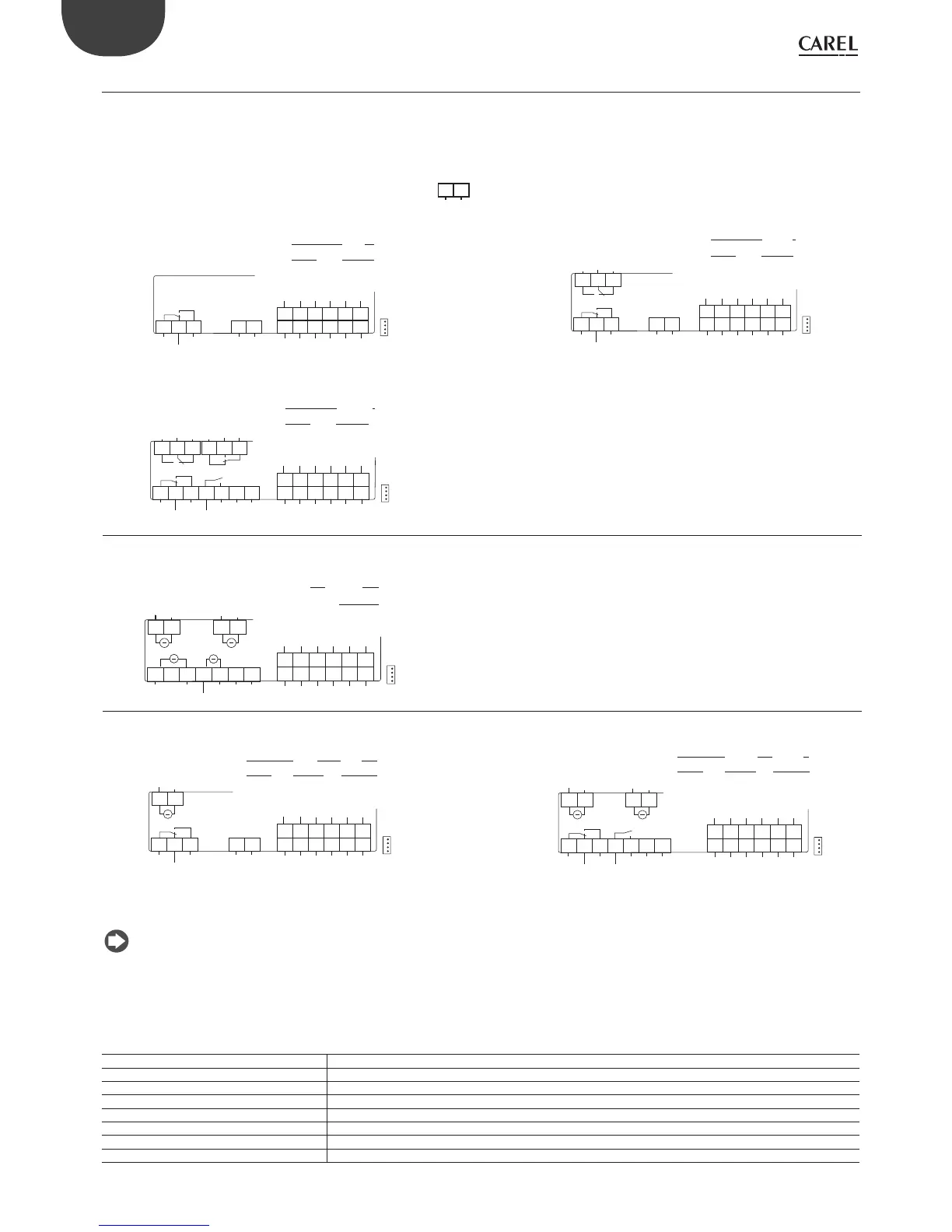
2.4 IR33/DN33 Universale with universal inputs - wiring diagrams
2.4.1 IR33
The models with 115/230 Vac and 24 Vac power supply have the same wiring diagram.
In the 230 Vac models, the line (L) is connected to terminal 7 and the neutral (N) to terminal 6. On the 24 Vac/Vdc models, make sure the polarity is correct
(G, G0).
POWER SUPPLY
G0 G
24 Vac/Vdc
IR33V9HR20 / IR33V9HB20/ IR33V9MR20 IR33W9HR20 / IR33W9HB20 / IR33W9MR20
SERIAL and KEY
19 20 21 22 23
25 26 27 28 29
24
30
DI1 GND -B1 +B1 B1 +5 V
DI2 GND
-B2 +B2 B2 +12 V
6 7
1 2 3
NC1
NO1C1
DO1
POWER
SUPPLY
EN60730-1
UL 873
~230 V
8 (4) A
8A 2FLA
12LRA
DO1
SERIAL and KEY
19 20 21 22 23
25 26 27 28 29
24
30
DI1 GND -B1 +B1 B1 +5 V
DI2
GND
-B2 +B2 B2 +12 V
6 7
1 2 3
NC1
NO1C1
DO1
POWER
SUPPLY
151413
NC2NO2 C2
DO2
EN60730-1
UL 873
~230 V
8 (4) A
8A 2FLA
12LRA
DO1/2
IR33Z9HR20 / IR33Z9HB20/ IR33Z9MR20
SERIAL and KEY
19 20 21 22 23
25 26 27 28 29
24
30
DI1 GND -B1 +B1 B1 +5 V
DI2
GND
-B2 +B2 B2 +12 V
6 7
1 2 3 4 5
NC1
NO1C1
NO3
C3
DO1 DO3
POWER
SUPPLY
151413
NC2
NO2
C2
181716
NC4
NO4
C4
DO2
DO4
EN60730-1
UL 873
~230 V
8 (4) A
8A 2FLA
12LRA
DO1...4
IR33A9HR20 / IR33A9HB20 / IR33A9MR20
SERIAL and KEY
19 20 21 22 23
25 26 27 28 29
24
30
DI1 GND -B1 +B1 B1 +5 V
DI2
GND
-B2 +B2 B2 +12 V
6 71 2 3 4 5
Y1G0 Y3
G0
POWER
SUPPLY
AO1
AO3
-+
-+
1413
Y2
1817
Y4
AO2 AO4
-+
-+
G0 G0
12 V MAX
20 mA MAX
AO1...4
SSR DC
IR33B9HR20/IR33B9HB20/IR33B9MR20 IR33E9HR20/ IR33E9HB20/ IR33E9MR20
SERIAL and KEY
19 20 21 22 23
25 26 27 28 29
24
30
DI1 GND -B1 +B1 B1 +5 V
-B2 +B2 B2 +12 V
6 71 2 3
NC1
NO1C1
DO1
POWER
SUPPLY
1413
Y2
AO2
-+
G0
DI2
GND
EN60730-1
UL 873
~230 V
8 (4) A
8A 2FLA
12LRA
DO1
0...10 V
5 mA MAX
AO4
DC
SERIAL and KEY
19 20 21 22 23
25 26 27 28 29
24
30
DI1 GND -B1 +B1 B1 +5 V
DI2 GND -B2 +B2 B2 +12 V
6 71 2 3 4 5
NC1
NO1C1
NO3
C3
DO1 DO3
POWER
SUPPLY
1413
Y2
1817
Y4
AO2 AO4
-+
-+
G0 G0
EN60730-1
UL 873
~230 V
8 (4) A
8A 2FLA
12LRA
DO1/3
0...10 V
5 mA MAX
AO2/4
DC
NOTE:
• All IR33 (temperature and universal inputs) and DN33 controllers (temperature inputs and universal inputs) have power terminals and outputs that
correspond in terms of position and numbering;
• the probe and digital input connections are the same for IR33 and DN33 models with universal inputs. Only the numbering of the terminals changes.
• To connect two-wire PT1000 probes, jumper B1 and +B1 (for probe 1) and B2 and +B2 (for probe 2)..
Key
POWER SUPPLY
Power supply
DO1/DO2/DO3/DO4
Digital output 1/2/3/4 (relays 1/2/3/4)
AO1/AO2/AO3/AO4
PWM output for controlling external solid state relays (SSR) or 0 to 10 Vdc analogue output
G0
PWM or 0 to 10 Vdc analogue output reference
Y1/Y2/Y3/Y4
PWM or 0 to 10 Vdc analogue output signal
C/NC/NO
Common/Normally closed/Normally open (relay output)
-B1, +B1, B1 / -B2, +B2, B2
Probe 1/Probe 2
DI1/DI2
Digital input 1/ Digital input 2
SSR
Relays,
0-10V
Relays
 Loading...


