49
ENG
ir33 universale +030220801 - rel. 2.1 - 21.06.2011
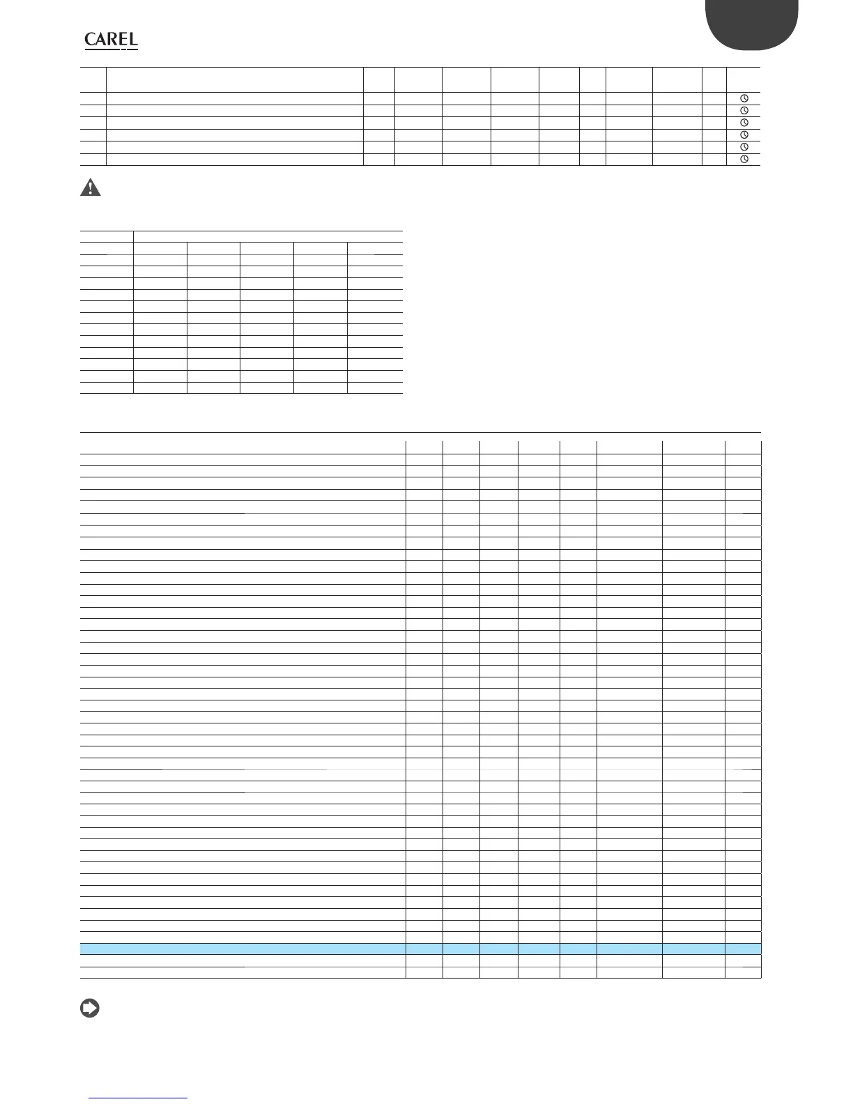
Par. Description Note Def Min Max UoM Type CAREL
SPV
ModBus® R/W Icon
y Date: year 0 0 99 year I 1 101 R/W
M Date: month 1 1 12 month I 2 102 R/W
d Date: day 1 1 31 day I 3 103 R/W
u Date: day of the week (Monday,-) 1 1 7 day I 4 104 R/W
h Hours 0 0 23 hour I 5 105 R/W
n Minutes 0 0 59 minutes I 6 106 R/W
Tab. 7.a
The default, minimum and maximum values of the alarm set points refer to temperature values. With universal inputs (voltage, current), these values
must be entered manually based on the range of measurement set.
(**) for alarms from digital input, the second unit of measure is used.
() DEFAULT PARAMETER TABLE
Model
Parameter V W Z/A B E
c3500000
c36 -100 -50 -25 -50 -25
C37 +100 +50 +25 +50 +25
c39 - 0 0 1 1
c40 - -100 -50 -100 -50
c41 - +50 +25 +50 +25
c43 - - 0 - 0
c44 - - -75 - -75
c45 - - +25 - +25
c47 - - 0 - 1
c48 - - -100 - -100
c49 - - +25 - +25
Tab. 7.b
7.1 Variables only accessible via serial connection
Description Def Min Max UOM Type CAREL SPV Modbus® R/W
Probe 1 reading 0 0 0 °C/°F A 2 2 R
Probe 2 reading 0 0 0 °C/°F A 3 3 R
Output 1 percentage 0 0 100 % I 127 227 R
Output 2 percentage 0 0 100 % I 128 228 R
Output 3 percentage 0 0 100 % I 129 229 R
Output 4 percentage 0 0 100 % I 130 230 R
Password 77 0 200 - I 11 111 R/W
Output 1 status 0 0 1 - D 1 1 R
Output 2 status 0 0 1 - D 2 2 R
Output 3 status 0 0 1 - D 3 3 R
Output 4 status 0 0 1 - D 4 4 R
Digital input 1 status 0 0 1 - D 6 6 R
Digital input 2 status 0 0 1 - D 7 7 R
Probe 1 fault alarm 0 0 1 - D 9 9 R
Probe 2 fault alarm 0 0 1 - D 10 10 R
Immediate external alarm (circuit 1) 0 0 1 - D 11 11 R
High temperature alarm, probe 1 0 0 1 - D 12 12 R
Low temperature alarm, probe 1 0 0 1 - D 13 13 R
Delayed external alarm (circuit 1) 0 0 1 - D 14 14 R
Immediate external alarm with manual reset (circuit 1) 0 0 1 - D 15 15 R
RTC fault alarm 0 0 1 - D 16 16 R
EEPROM unit parameters alarm 0 0 1 - D 17 17 R
EEPROM operating parameters alarm 0 0 1 - D 18 18 R
Maximum time in calculation of PID parameters 0 0 1 - D 19 19 R
PID gain null 0 0 1 - D 20 20 R
PID gain negative 0 0 1 - D 21 21 R
Integral & derivative time negative 0 0 1 - D 22 22 R
Maximum time in calculation of continuous gain 0 0 1 - D 23 23 R
Starting situation not suitable 0 0 1 - D 24 24 R
Immediate alarm from digital 1 (circuit 1) 0 0 1 - D 42 42 R
Immediate alarm from digital 1 with manual reset (circuit 1) 0 0 1 - D 43 43 R
Delayed alarm from digital 1 (circuit 1) 0 0 1 - D 44 44 R
Immediate alarm from digital 2 (circuit 1) 0 0 1 - D 45 45 R
Immediate alarm from digital 2 with manual reset (circuit 1) 0 0 1 - D 46 46 R
Delayed alarm from digital 2 (circuit 1) 0 0 1 - D 47 47 R
High temperature alarm, probe 2 0 0 1 - D 49 49 R
Low temperature alarm, probe 2 0 0 1 - D 50 50 R
Delayed signal only alarm 0 0 1 - D 51 51 R
Immediate signal only alarm 0 0 1 - D 52 52 R
Immediate external alarm (circuit 2) 0 0 1 - D 53 53 R
Delayed external alarm (circuit 2) 0 0 1 - D 54 54 R
Immediate external alarm with manual reset (circuit 2) 0 0 1 - D 55 55 R
Probe reading alarm 0 0 1 - D 56 56 R
Switch controller On/O 0 0 1 - D 36 36 R/W
Reset alarm 0 0 1 - D 57 57 R/W
Tab. 7.c
Type of variable: A= analogue, D= digital, I= integer
SVP= variable address with CAREL protocol on 485 serial card, ModBus® : variable address with ModBus® protocol on 485 serial card.
The selection between CAREL and ModBus® protocol is automatic. For both of them the speed is xed to 19200 bit/s.
The devices connected to the same network must have the following serial parameter settings: 8 data bits; 1 start bit; 2 stop bits; parity disabled; baud
rate19200. For CAREL and Modbus® the analogue variables are expressed in tenths (e.g.: 20.3 °C= 203)
 Loading...


