34
ENG
ir33 universale +030220801 - rel. 2.1 - 21.06.2011
5.7 Additional remarks on special operation
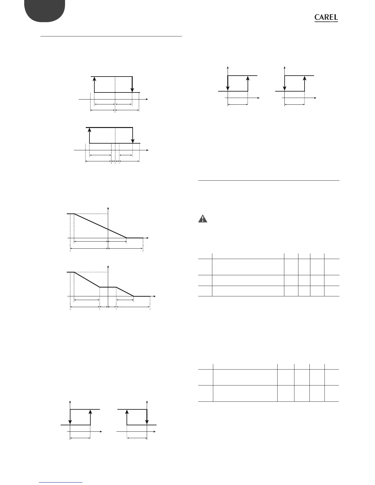
Dead zone P3
In modes 3, 4 and 5 there is a dead zone de ned by P3. The activation or
deactivation points cannot be positioned inside the dead zone: if these
are identi ed in the zone before and after the set point, the instrument
automatically increases the hysteresis of the output involved by double
the value of P3.
ON
OFF
St1
B1
P1
P1
b
a
ON
OFF
St1
B1
P1 P3 P3
P1
b
a
Fig. 5.u
The PWM (or analogue) outputs will follow the operation indicated in
the gure. In practice, in the dead zone the output maintains the level of
activation unchanged.
100%
OUT1
0%
St1
P1
P1
ba
100%
OUT1
0%
St1
P1 P3
P3 P1
ba
Fig. 5.v
Mode 6 sees the outputs linked to St1 with “direct” logic (“activation”
positive and “di erential/logic” negative) when digital input 1 is open. The
closing of digital input 1 forces the outputs to depend on St2 and P2,
and the logic becomes “reverse”, by inverting of sign of the “activation”
and “di erential/logic” parameters (reading the values of the parameters
does not depend on the status of the digital input: these only change as
regards the algorithm). When c33=1.
The outputs with dependence 16 will have the e ect shown in the gure
when ID1 switches.
DEPENDENCE= 16
INPUT DI1 OPEN INPUT DI1 CLOSED
ON
OFF
St1
B1
P1
ON
OFF
St2
B1
P2
Fig. 5.w
Modes 7 and 8. The outputs with “dependence”=17 will have the e ect
shown in the gure when ID1 switches.
These modes in fact do not allow changes to the logic. The alarm outputs
(“dependence”=3 to 14, 19 to 29) do not depend on digital input 1.
DEPENDENCE= 17
INPUT DI1 OPEN INPUT DI1 CLOSED
ON
OFF
St1
B1
P1
ON
OFF
St2
B1
P2
Fig. 5.x
Modes 1 & 2 in di erential operation (c19=1).
Similarly to the previous case, when c33=1 the outputs with “dependence”
= 2 no longer have the compensation function.
Modes 1 and 2 with “compensation” operation (c19=2, 3, 4).
Like the previous case, when c33=1 the compensation function is no
longer active on outputs with “dependence” setting 2.
5.8 Outputs and inputs
5.8.1 Relay digital outputs (par. c6,c7,d1,c8,c9,c11)
The parameters in question concern the minimum on or o times of the
same output or di erent outputs, so as to protect the loads and avoid
swings in control.
For the times set to become immediately operational, the controller
needs to be switched o and on again. Otherwise, the timers will
become operational when the controller is next used, when the internal
timer is set.
5.8.2 Relay output protector (parameters c7,c8,c9)
Par. Description Def Min Max UoM
c7 Minimum time between activations
of the same relay output
Validity: c0 ≠ 4
0 0 15 min
c8 Minimum relay output o time
Validity: c0≠ 4
0 0 15 min
c9 Minimum relay output on time
Validity: c0 ≠ 4
0 0 15 min
Tab. 5.m
• c9 de nes the minimum time the output is activated, regardless of the
request.
• c8 de nes the minimum time the output is deactivated, regardless of
the request
• c7 establishes the minimum time between two following activations
of the same output.
5.8.3 Other relay output protectors
(parameters c6,d1)
Par. Description Def Min Max UoM
c6 Delay between activations of 2
di erent relay outputs
Validity: c0 ≠ 4
5 0 255 s
d1 Minimum time between deactiva-
tions of 2 di erent relay outputs
Validity: c0≠ 4
0 0 255 s
Tab. 5.n
• c6 establishes the minimum time that must elapse between successive
activations of two di erent relay outputs. Activation is delayed to avoid
overloads on the line due to starting devices too close together or
simultaneously.
• d1 establishes the minimum time that must elapse between
deactivations of two di erent outputs.
 Loading...


