35
ENG
ir33 universale +030220801 - rel. 2.1 - 21.06.2011
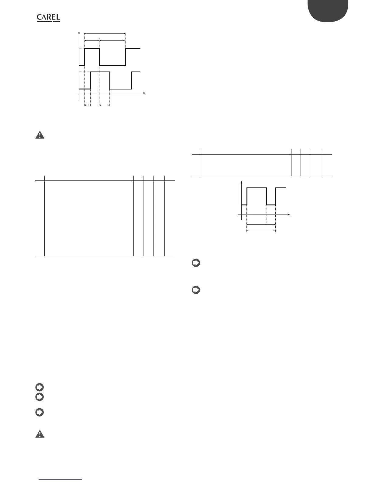
ON
OUT1
OUT2
OFF
t
c6
d1
c9
c7
c8
ON
OFF
Fig. 5.y
Key
t= time
c6, c7, c8, c9 & d1 are not operative for the PWM outputs.
5.8.4 Rotation (parameter c11)
This allows the control outputs to change activation and deactivation
priority: based on the requests dictated by the controller, the output that
has been active longest is deactivated, or the output that has been o
longest is activated.
Par. Description Def Min Max UM
c11 Output rotation
0=Rotation not active
1=Standard rotation (on 2 or 4 relays)
2=Rotation 2+2
3=Rotation 2+2 (COPELAND)
4=Rotation of outputs 3 & 4, not 1 & 2
5=Rotation of outputs 1 & 2, not 3 & 4
6=Separate rotation of pairs 1,2
(between each other) and 3,4
7= Rotation of outputs 2,3,4, not 1
Validity : c0=1,2,7,8 & c33=0
8= Rotation of outputs 1 and 3, not 2 and 4
Validity : c0=1, 2, 7, 8 and c33= 0
00 7 -
Tab. 5.o
Rotation 2+2 on 4 outputs (c11=2) has been designed to manage capacity-
controlled compressors. Outputs 1 and 3 activate the compressors, outputs
2 and 4 the capacity control valves. Rotation occurs between outputs 1 and
3, while the valves are energised (relays ON) to allow the operation of the
compressors at maximum capacity. Valve 2 is linked to output 1 and valve
4 to output 3.
The rotation 2+2 DWM Copeland on 4 outputs (c11=3) is similar to the
previous rotation, with the opposite logic for managing the valves. The
valves are in fact normally energised (capacity controlled compressor) and
are de-energised (relays OFF) when the compressor needs to operate at full
power. A normal activation sequence is:
1 o , 2 o , 3 o , 4 o
1 on, 2 on, 3 o , 4 o
1 on, 2 o , 3 o , 4 o
1 on, 2 o , 3 on, 4 on
1 on, 2 o , 3 on, 4 o
As before, in this case too outputs 1 and 3 control the compressors,
outputs 2 and 4 the corresponding solenoid valves.
The parameter has no e ect on controllers with 1 output.
In the models with two outputs(W), rotation is standard even when
c11=2 or 3;
The connection in the 2+2 con guration is as follows: OUT1 = Comp.
1, OUT2 = Valve 1, OUT3 = Comp. 2, OUT4 = Valve 2.
Pay careful attention when programming the parameters, as the
controller rotates the outputs according to the logic described
above, regardless of whether these are control outputs (PWM) or alarm
outputs. If there is at least one PWM or 0 to 10 Vdc output, rotation is
never active, except for on DN/IR33 model E with c11=8..
Example a: if there are two alarm and two control outputs, rotation must
be set so as to only rotate the control outputs.
Example b: to control a chiller with three compressors, rotation mode 7
can be set, reserving outputs 2, 3 & 4 for the compressors, while output
1 can be unconnected or used as an auxiliary output or alarm output.
5.8.5 SSR (solid state relay) digital outputs
When control is required using on one or more PWM outputs, the
solution with relays becomes impractical if the changeover times are not
quite high (at least 20 seconds), otherwise the life of the relays will be
reduced. In these cases, solid state relays (SSR) can be used, managed
according to the speci c application.
5.8.6 PWM cycle time (parameter c12)
This represents the total time of the PWM cycle; in fact, the sum of the
on time (tON) and the o time (tOFF) is constant and equal to c12. The
ratio between ton and to is established by the control error, that is, the
deviation from the set point, referred (as a percentage) to the di erential
linked to the output. For further details, see mode 4.
Par. Description Def Min Max UM
c12 PWM cycle time
Validity: c0=4;
In special operation c12
is active in any mode if “type of output”=1
20 0.2 999 s
Tab. 5.p
t
c12
ton to
ON
OFF
Fig. 5.z
Key
t= Time
As the action of PWM operation is modulating, PID control can be
fully exploited, so that the value coincided with the set point or falls
inside the dead zone.
The minimum on time (ton) calculable and the maximum de nition
achievable for ton is 1/100 of c12(1%).
5.8.7 0 to 10 Vdc analogue outputs
When the application requires one or more 0 to 10 Vdc analogue outputs,
the following controllers should be used:
IR33B7**** (1 relay + 1 x 0 to 10Vdc)
IR33E7**** (2 relays + 2 x 0 to 10Vdc)
DN33B7**** (1 relay + 1 x 0 to 10Vdc)
DN33E7**** (2 relays + 2 x 0 to 10Vdc)
In this case too, the system operates with a voltage that ramps from 0 to 10 Vdc.
5.8.8 Analogue inputs
See the start of the chapter, under the paragraph on “Probes”.
 Loading...


