39
ENG
ir33 universale +030220801 - rel. 2.1 - 21.06.2011
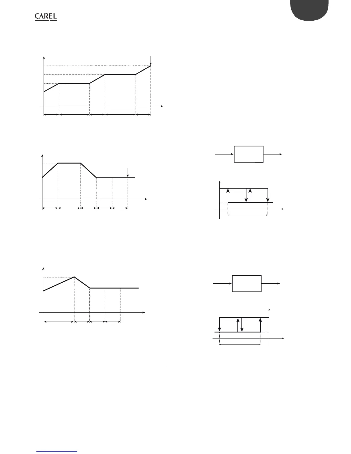
Example 2: Heating cycle with intermediate pauses
At the end of Step5, the operating cycle ends automatically and control
resumes based on Set1.
automatically exit the operating cycle
t
T
STEP1
P71=30’
P72=SetA
STEP2
P73=40’
P74=SetA
STEP3
P75=30’
P76=SetB
40’
SetA
SetB
30’ 30’
40’
STEP4
P77=40’
P78=SetB
30’
STEP5
P79=30’
P80=SetC
SetC
Set1
Fig. 6.b
Example 3: Low pasteurisation cycle
At the end of Step5, the operating cycle ends automatically and control
resumes based on Set1.
t
T
STEP1
P71=30’
P72=Set2
STEP2
P73=45’
P74=Set2
STEP3
P75=30’
P76=Set1
STEP4
P77=1’
P78=Set1
45’
Set1
SetA
30’ 30’ 1’
STEP5
P79=1’
P80=Set1
1’
Fig. 6.c
Example 4: High pasteurisation cycle
In this example, having set the time for the last step to “0”, the operating
cycle does not end until the operator intervenes, and temperature
control continues in nitely. As the temperature for in nite temperature
control is equal to the temperature set for Set1, the system will behave as
if it were in normal control, however the display will show CL5 to indicate
that the operating cycle is still in progress.
t
T
STEP1
P71=60’
P72=SetA
STEP2
P73=30’
P74=Set1
STEP3
P75=1’
P76=Set1
Set1
SetA
60’
30’ 1’
STEP4
P77=1’
P78=Set1
1’
STEP5
P79=0
P80=Set1
Fig. 6.d
Key
T= temperature
t = time
6.5 Operation with probe 2
Installing probe 2 allows various types of operation to be enabled,
selected using parameter c19.
6.5.1 Di erential operation (parameter c19=1)
The second probe (B2) must be installed. Control is performed by
comparing the set point St1 against the di erence between the two
probes (B1-B2). In practice, the controller acts so that the di erence B1-B2
is equal to St1. As mentioned, the management of the second probe is
only available in modes c0=1 & 2.
“Direct” operation (c0=1) is suitable for applications in which the controller
needs to stop the di erence B1-B2 from increasing.
“Reverse” operation (c0=2), on the other hand, stops the di erence B1-B2
from decreasing. Below are some examples of applications.
Example 1:
A refrigeration unit with 2 compressors must lower the temperature of
the water by 5°C.
Introduction: having selected a controller with 2 outputs to manage the
2 compressors, the rst problem to be faced relates to the positioning
of probes B1 and B2. Remember that any temperature alarms can only
refer to the value read by probe B1. The example indicates the inlet
temperature as T1 and the outlet temperature as T2.
Solution 1a: install B1 on the water inlet if it is more important to control
the inlet temperature T1; that will allow alarm signals, where necessary
delayed, relating to a “High” inlet temperature T1. For example, when
B1=T1 the set point corresponds to “B1-B2”, i.e. “T1-T2”, and must be equal
to +5°C (St1=5). The operating mode will be “reverse” (c0=2), given that
the controller activates the outputs as the value of “T1-T2” decreases,
and tends towards 0. Choosing a di erential equal to 2°C (P1=2), a high
temperature threshold equal to 40°C (P26=40) and a delay of 30 minutes
(P28=30), the operation will be as described in the following gure.
B1 (T1)B2 (T2)
CHILLER
St1=5
OUT2 OUT1
Mod. W
B1-B2
P1
ON
OFF
Fig. 6.e
Solution 1b: if on the other hand priority is attributed to T2 (e.g. “Low
temperature” threshold 6°C with a one minute delay), the main probe,
B1, must be set as the outlet temperature. With these new conditions,
the set point St1, equal to “B1-B2”, i.e. ‘T2-T1’, must now be set to -5°C.
The operating mode will be “direct” (c0=1), given that the controller must
activate the outputs as the value of ‘T2-T1’ increases, and from -5 tends
towards 0. P25=6 and P28=1(min) activate the “Low temperature” alarm,
as shown in the new control logic diagram:
B2 (T1)B1 (T2)
CHILLER
St1=-5
OUT1 OUT2
Mod. W
B1-B2
P1
ON
OFF
Fig. 6.f
Example 1 (continued)
Example 1 can be resolved using “special” operation (c33=1). Starting
from solution 1b (T2 must be 5°C less than T1). The main probe is located
at the outlet (T2 =B1).
These requirements also need to be satis ed:
• the outlet temperature T2 must remain above 8°C;
• if T2 remains below 6°C for more than one minute, a “Low temperature”
alarm must be signalled.
Solution: use a controller with 4 outputs (IR33Z****); two outputs are
used for control (OUT3 and OUT4), and one for the remote alarm signal
(OUT1). OUT2 will be used to deactivate outputs OUT3 and OUT4 when
T2< 8°C. To do this, simply connect OUT2 in series with OUT3 and OUT4,
then make OUT2 active only when B1 (T2) is greater than 8°C.
 Loading...


