40
ENG
ir33 universale +030220801 - rel. 2.1 - 21.06.2011
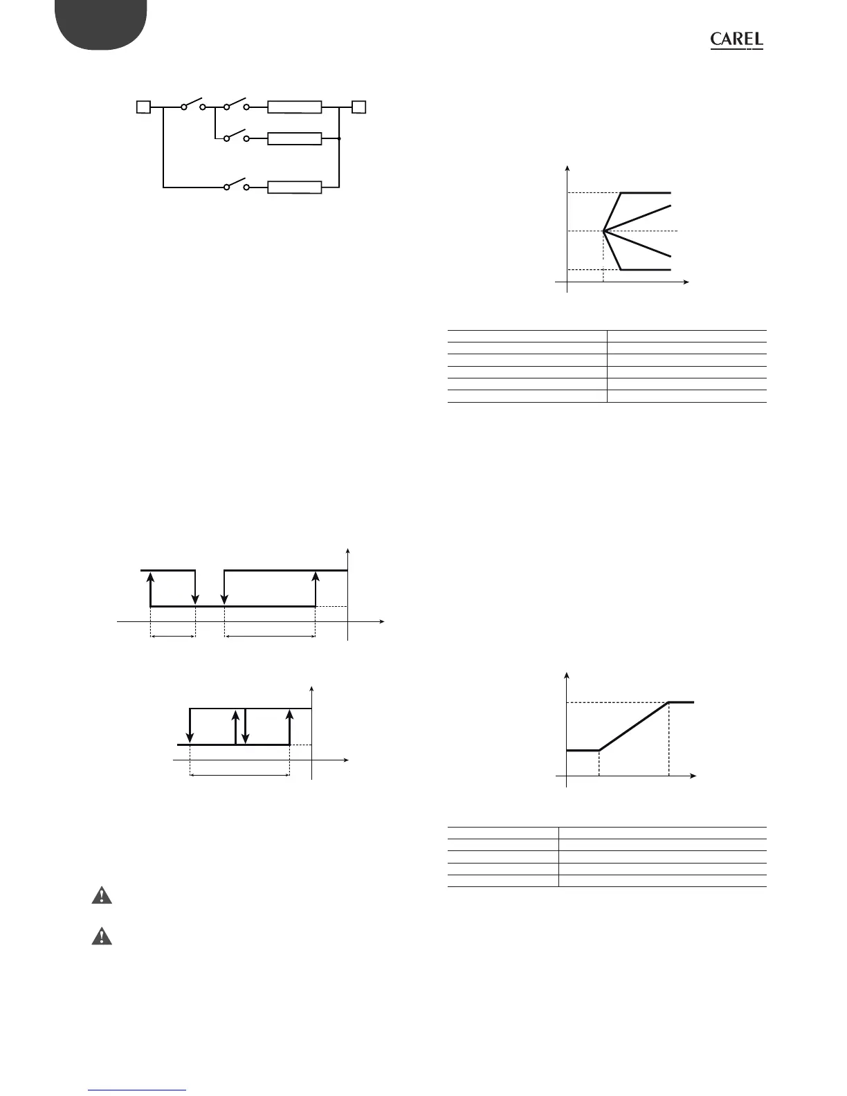
6.5.3 Compensation in cooling (parameter c19=2)
Compensation in cooling may either increase or decrease the value of
St1, depending on whether c4 is positive or negative.
St1 only changes if the temperature B2 exceeds St2:
• if B2 is greater than St2 then: e ective St1 = St1 + (B2-St2)*c4
• if B2 is less than St2: e ective St1 = St1
St2
c4= 2
c4=+0,5
c4=-0,5
B2
c22
St1_comp
c21
St1
c4= -2
Fig. 6.i
Key:
St2 Activation set point 2
St1_comp E ective set point 1
B2 Outside probe
c4 Authority
c21 Minimum value of set point 1
c22 Maximum value of set point 1
Example 1:
The bar in a service station needs to be air-conditioned so that the
temperature is summer is around 24°C. To prevent the customers, who
only stay for a few minutes, from experiencing considerable di erences in
temperature, the inside temperature is linked to the outside temperature,
that is, it increases proportionally up to a maximum value of 27°C, when
the outside temperature is 34°C or higher.
Solution: a controller is used to manage a direct expansion air/air unit.
The main probe B1 is installed in the bar, the controller works in mode
c0=1 (direct) with set point=24°C (St1=24) and di erential e.g. 1°C (P1=1).
To exploit compensation in cooling mode, install probe B2 outside and
set c19=2. Then set St2=24, given that the requirement is to compensate
set point 1 only when the outside temperature exceeds 24 °C. The
authority c4 must be 0.3, so that with variations in B2 from 24 to 34°C,
St1 changes from 24 to 27°C. Finally, select c22=27 to set the maximum
value for the e ective St1. The graph shows how St1 changes according
to the temperature B2.
St1_comp
c22=27
24
St2=24 34 B2
c4=0,3
Fig. 6.j
Key:
St2 Activation set point 2
St1_comp E ective set point 1
B2 Outside probe
c4 Authority
c22 Maximum value of set point 1
Example 2:
This example involves compensation in cooling with a negative c4.
The air-conditioning system consists of a water chiller and some fan
coil units. When the outside temperature is below 28°C, the chiller
inlet temperature can be xed at St1=13°C. If the outside temperature
increases, to compensate for the greater thermal load, the inlet
temperature can be lowered down to a minimum limit of 10°C, reached
when the temperature is greater than or equal to 34°C.
Solution: the parameters to be set on the controller, with one or more
outputs in relation to the characteristics of the chiller, will be as follows:
• c0=1, main probe B1 on the chiller inlet, with a main control set point
Set c33=1: the changes to be made to the special parameters are:
L Ncompressor 1
OUT2OUT3
OUT4
OUT1
compressor 2
alarm
Fig. 6.g
Output 1: must be programmed as an alarm output that is active only
for the “Low temperature” alarm. Set “dependence”=c34, which changes
from 1 to 9 (or 10 to use normally ON relays). The other parameters for
output 1 are not relevant and remain unchanged.
Output 2: this becomes detached from di erential operation, changing
the “dependence” from 1 to 2: “dependence”=c38=2. The logic is “direct”
and includes all of P2, therefore “activation” =c40 becomes 100, and
“di erential/logic”=c41 becomes -100. St2 will obviously be set to 8 and
P2 represents the minimum variation required to restart control, once it
has stopped due to “Low temperature”, e.g. P2=4.
Output 3 and Output 4: in the controllers with 4 outputs, mode 1 assigns
each output an hysteresis of 25% of the di erential P1. In the example,
considering that 2 outputs are used for control, the hysteresis for
each output must be 50% of P1. The “activation” and “di erential/logic”
parameters for the outputs must be changed to suit the new situation.
In practice, this means setting:
Output 3:
“activation”=c44 changes from 75 to 50
“di erential/logic”=c45, changes from -25 to -50.
Output 4:
“activation”=c48 remains at 100
“di erential/logic” = c49 changes from -25 to -50.
The diagram summarises the controller operating logic.
P25=6St2=8
OUT1 (LOW ALARM) OUT2
Mod. Z
B1 (T2)
P2P27
ON
OFF
St1=-5
OUT3 OUT4
Mod. W
B1-B2
P1
ON
OFF
Fig. 6.h
6.5.2 Compensation
The compensation function is used to modify the control set point St1
according to the reading of the second probe B2 and the reference set point
St2. Compensation has a weight equal to c4, called the “authority”.
The compensation function can only be activated when
c0=1,2.
When compensation is in progress, parameter St1 remains at the set
value; on the other hand, the operating value of St1 changes, known
as the e ective St1, that is, the value used by the control algorithm. The
e ective St1 is also restricted by the limits c21 and c22 (minimum and
maximum value of St1); these two parameters guarantee that St1 does
not reach undesired values.
 Loading...


