19
ENG
ir33 universale +030220801 - rel. 2.1 - 21.06.2011
3. USER INTERFACE
The front panel contains the display and the keypad, made up of 4 buttons, that, when pressed alone or combined with other buttons, are used to program
the controller.
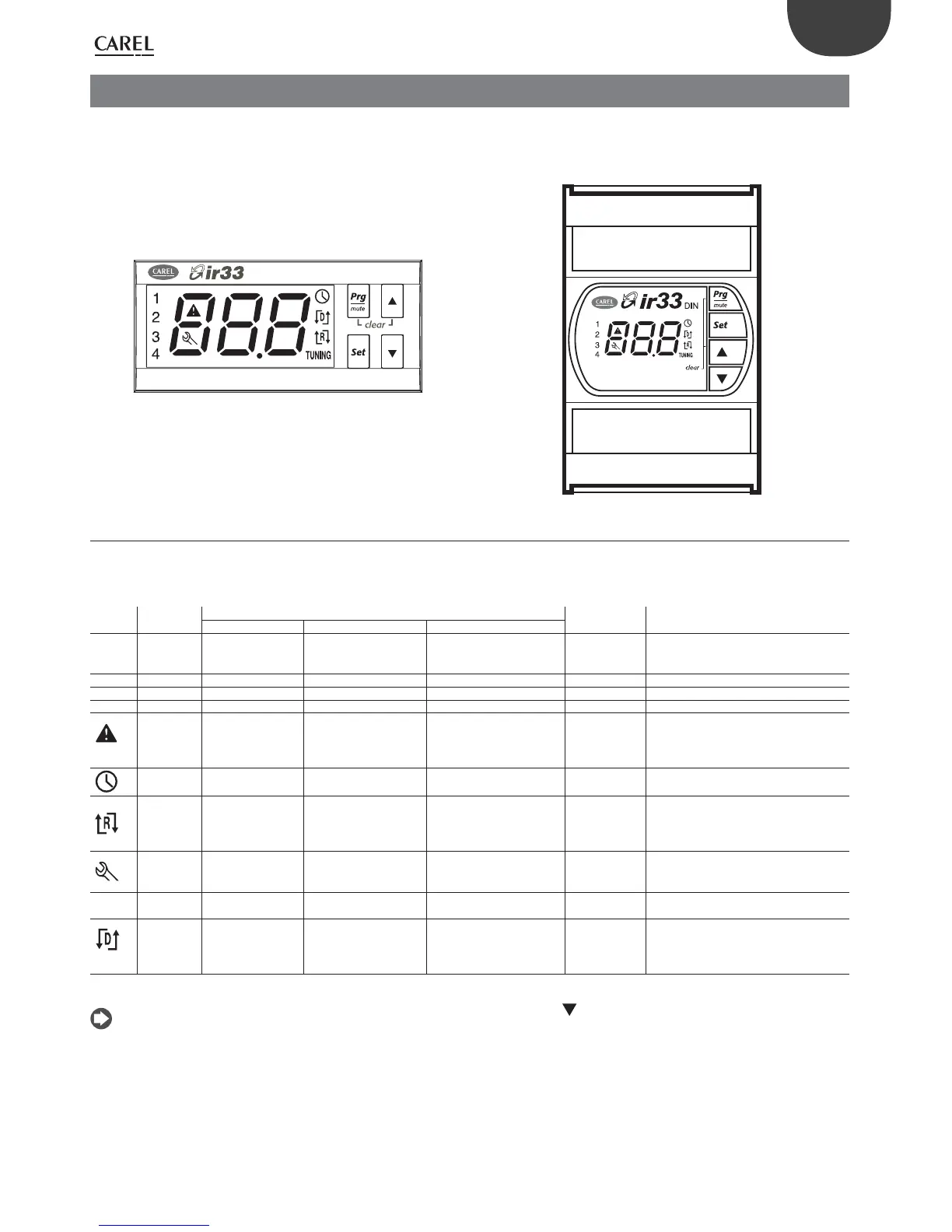
IR33 Universal front panel DN33 Universale
Fig. 3.a Fig. 3.b
3.1 Display
The display shows the temperature in the range –50°C to +150°C in the models with temperature inputs only and in the range -199 to +800°C in the models
with universal inputs. The temperature is displayed with resolution to tenths between –19.9°C & + 99.9°C. Alternatively, it can show the value of one of the
analogue or digital inputs, or the set point (see parameter c52). During programming, it shows the codes and values of the parameters.
Icon Function
Normal operation
Start up Notes
ON OFF BLINK
1
Output 1 Output 1 active Output 1 not active Output 1 request Flashes when activation is delayed or
inhibited by protection times, external
disabling or other procedures in progress.
2 Output 2 Output 2 active Output 2 not active Output 2 request See note for output 1
3 Output 3 Output 3 active Output 3 not active Output 3 request See note for output 1
4 Output 4 Output 4 active Output 4 not active Output 4 request See note for output 1
ALARM No alarm present Alarms in progress Flashes when alarms are active during nor-
mal operation or when an alarm is active
from external digital input, immediate or
delayed.
CLOCK
Clock alarm
Operating cycle active
ON if Real Time
Clock present
REVERSE Reverse operation
active
Reverse operation not
active
PWM /0 to 10 Vdc outputs Signals operation of the unit in “reverse”
mode, when at least one relay with “rever-
se” operation is active. Flashes if PWM/0 to
10 Vdc outputs.
SERVICE No malfunction Malfunction (e.g. E2PROM
error or probes faulty). Con-
tact service
TUNING
TUNING AUTO-Tuning function
not enabled
AUTO-Tuning function
enabled
On if the AUTO-Tuning function is active
DIRECT Direct operation
active
Direct operation not
active
PWM /0 to 10 Vdc outputs Signals operation of the unit in “direct”
mode, when at least one relay with “direct”
operation is active. Flashes if PWM/0 to 10
Vdc outputs.
Tab. 3.a
The user can select the standard display by suitably setting parameter c52, or by pressing (DOWN) to select one of the possible options (b1, b2,
di1, di2, St1, St2) and con rming by pressing Set. See paragraph 3.4.11.
 Loading...


