26
ENG
ir33 universale +030220801 - rel. 2.1 - 21.06.2011
5. FUNCTIONS
In the tables, the parameters that are repeated highlight the
di erences in settings between the models with universal inputs
and the models with temperature inputs only.
5.1 Temperature unit of measure
On IR33 Universale the temperature unit of measure can be changed
from degrees Celsius to degrees Fahrenheit using parameter c18.
Par. Description Def Min Max UOM
c18 Temperature unit of measure
0=°C; 1=°F
001-
Tab. 5.a
The models with universal inputs can be connected to PT100 or PT1000
probes and thermocouples, and operate with temperatures from -199°C
to 800°C, consequently the parameters corresponding to the minimum
and maximum limits of the set point are di erent. See the table below.
The function works as follows:
1. in degrees Celsius the settable temperature range is -199T800°C;
2. in degrees Fahrenheit the settable temperature range is -199T800°F.
Due to the conversion using the formula:
T(°F)=T(°C) x1.8 + 32
the settable temperature range in degrees Celsius is wider than in
degrees Fahrenheit.
T (°C)
-199
-128
426
800
T (°F)
-199
800
Fig. 5.a
• If the display is showing the reading of probe 1 or 2 in the range between
-199°C and -128°C or between 426°C and 800°C, and the unit is set to
degrees Fahrenheit, the error E01 or E02 will be shown;
• If the controller is working in degrees Celsius and the temperature set point
is set over 426°C or below -128°C, if then switching to degrees Fahrenheit
the set point will be limited to 800°F and -199°F respectively.
5.2 Probes (analogue inputs)
The probe parameters are used to :
• set the type of probe
• set the o set to correct the probe reading (calibration)
• set the maximum/minimum current/voltage value;;
• activate a lter to stabilise the reading
• set the unit of measure shown on the display
• enable the second probe and the compensation function. IR33
Universale models with universal inputs have wider ranges for NTC
and PT1000 temperature probes than the IR33 Universale models with
temperature only. In addition these can use thermocouples, active
probes and voltage and current inputs, as shown in the table.
Par. Description Def Min Max UoM
c13 Probe type
0= Standard NTC range(-50T+90°C)
1= NTC-HT enhanced range(-40T+150°C)
2= Standard PTC range(-50T+150°C)
3= Standard PT1000 range(-50T+150°C)
00 3 -
c13
Probe type
0= NTC range (-50T+110°C)
1= NTC-HT range (-10T+150°C)
2= PTC range (-50T+150°C)
3= PT1000 range (-50T+200°C)
4= PT1000 range (-199T+800°C)
5= Pt100 range (-50T+200°C)
6= Pt100 range (-199T+800°C)
7= J thermocouple range (-50T+200°C)
8= J thermocouple range (-100T+800°C)
9= K thermocouple range (-50T+200°C)
10= K thermocouple range (-100T+800°C)
11= 0 to 1 Vdc input
12=- 0.5 to 1.3 Vdc input
13= 0 to 10 Vdc input
14= 0 to 5 Vdc ratiometric
15= 0 to 20 mA input
16= 4 to 20 mA input
0 0 16 -
P14
Probe 1 calibration
0 (0) -20 (-36) 20 (36) °C(°F)
P15
Probe 2 calibration
0 (0) -20 (-36) 20 (36) °C(°F)
P14
Probe 1 calibration
0 (0) -99,9
(-179)
99,9
(179)
°C(°F)
P15
Probe 2 calibration
0 (0) -99,9
(-179)
99,9
(179)
°C(°F)
c15
Minimum value for probe 1 with cur-
rent/voltage signal
0 -199 c16 -
c16
Maximum value for probe 1 with
current/voltage signal
100 c15 800 -
d15
Minimum value for probe 2 with cur-
rent/voltage signal
0 -199 d16 -
d16
Maximum value for probe 2 with
current/voltage signal
100 d15 800 -
c17
Probe disturbance lter
4 1 15 -
Tab. 5.b
When a probe with current/voltage signal is selected, the unit of
measure must be left at °C (C18=0).
Parameter c13 de nes the type of probe 1 (B1) and any probe 2 (B2).
For controllers with universal inputs, the corresponding selections
are highlighted in the table. Parameters P14 and P15, for probe 1 and
probe 2 respectively, are used to correct the temperature measured by
the probes indicated on the display, using an o set: the value assigned
to these parameters is in fact added to (positive value) or subtracted
from (negative value) the temperature measured by the probes. When
pressing Set, after having entered the value, the display does not show
the parameter, but rather immediately shows the new value of the probe
reading being calibrated. This means the result of the setting can be
checked immediately and any adjustments made as a consequence.
Press Set again to access the parameter code and save the value. For
probes with current/voltage signals, parameters c15, c16 for probe 1 and
d15, d16 for probe 2 are used to “scale” the probe output signal. The value
of parameters P14, P15 is added after this operation.
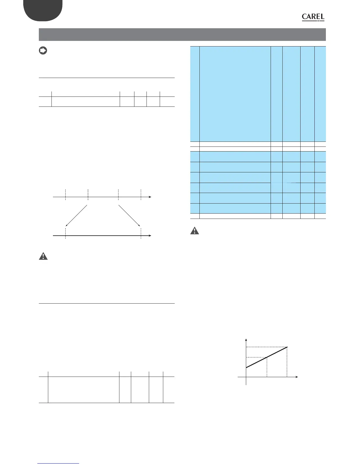
Example: 0 to 10 Vdc input on B1, c15=30, c16=90, P14= 0
90
Display
Visualization
(P14=0)
B1
30
60
5V0 10V
Fig. 5.b
Consequently, 0 V will be as displayed 30 and 10V will be displayed as 90.
These are also the values used for control.
Parameter c17 de nes the coe cient used to stabilise the temperature
reading. Low values assigned to this parameter allow a prompt response
of the sensor to temperature variations, but the reading becomes more
sensitive to disturbance. High values slow down the response, but
guarantee greater immunity to disturbance, that is, a more stable and
more precise reading.
 Loading...


