16
ENG
ir33 universale +030220801 - rel. 2.1 - 21.06.2011
2.6 Connection diagrams
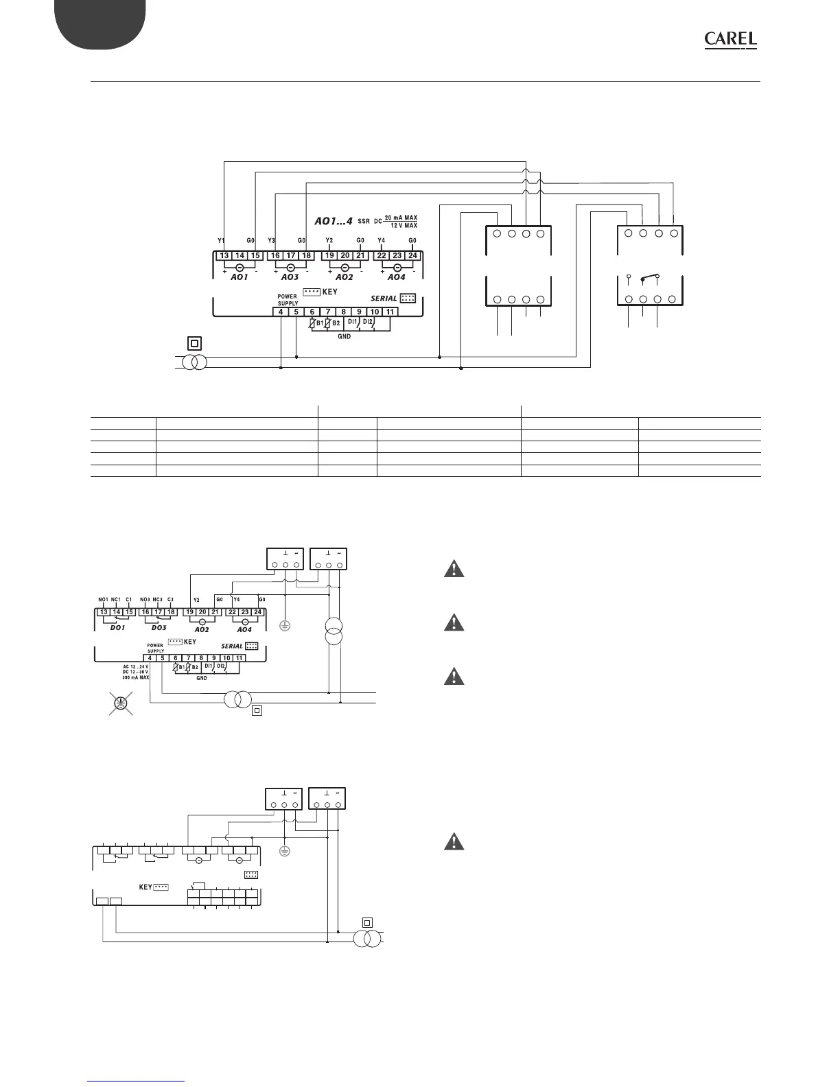
2.6.1 Connection to the CONV0/10VA0 and CONVONOFF0 modules (accessories)
The CONV0/10AVA0 and CONVONOFF0 modules convert a PWM output for SSR to a 0 to 10 Vdc analogue output and ON/OFF relay output respectively.
Below is an example of an application that uses model DN33A7LR20. Note that the same controller can thus have 3 di erent types of outputs. If only the
0 to 10 Vdc analogue output and the relay output are required, models DN33E7LR20 or DN33E9MR20 can be used; the wiring diagram is shown below.
Y+ Y-
G0
G
Input signal
G0 4-20mA
6LJQDORXWSXW
G0 0-10Vdc
6LJQDORXWSXW
CONV0/10A0
9DF
9DF
Y+
Y-
G0
G
Input signal
No
2XWSXW
Com
Nc
CONVONOFF0
Fig. 2.a
Key
CONV0/10A0 & CONVONOFF modules CONV0/10A0 module CONVONOFF module
Terminal Description Terminal Description Terminal Description
1 24 Vac power supply 5 0 to 10 Vdc output reference 5 Normally open
2 Power supply reference 6 0 to 10 Vdc output 6 Common
3 PWM control signal (+) 7 4 to 20 mA output reference 7 Normally closed
4 PWM control signal (-) 8 4 to 20 mA output 8 Not connected
The control signal to terminals 3 & 4 on the CONV0/10VA0 and CONVONOFF modules is optically-isolated. This means that the power supply (G , G0) can be
in common with the power supply to the controller.
-
+
-
+
G0
12/24 Vac
115/230 Vac
GY
G0 GY
ATTUATORE 1
ACTUATOR 1
ATTUATORE 2
ACTUATOR 2
NO!
PE
24 Vac
Fig. 2.b
C1NO1 NC1
DO1
SERIAL
DI1 GND -B1 +B1 B1 +5 V
DI2
GND
-B2 +B2 B2 +12 V
AO2
AO4
-+
-
+
G0Y2 G0Y4
C3NO3 NC3
DO3
AC 24 V/ DC 24 V 450 mA MAX
G
G0
G0
24 Vac
230 Vac
G
G0
GY
G0 GY
ATTUATORE 1
ACTUATOR 1
ATTUATORE 2
ACTUATOR 2
24 Vac
Fig. 2.c
TEMPERATURE INPUTS
On models B and E with direct or alternating current power supply,
the reference (G0) for the 0 to 10 Vdc output and the power supply
reference cannot be in common.
If the actuators connected to the analogue outputs require, the
earth connection (PE) is performed making sure that this is on G0 of
the ,outputs as shown in the gure.
For models DN33x(B, E)7LR20 and IR33x(B, E)7LR20 the diagram
shown must be adhered to, otherwise the instrument may be
damaged irreversibly.
UNIVERSAL INPUTS
For models B and E with DC or AC power supply, the reference (G0)
for the 0 to 10 Vdc output and power supply reference may be in
common, make sure the polarity is observed for 24 V power supply (G,
G0). This allows just one transformer to be used.
 Loading...


