25
ENG
ir33 universale +030220801 - rel. 2.1 - 21.06.2011
4. COMMISSIONING
4.1 Con guration
The con guration parameters should be set when commissioning the
controller, and involve:
• serial address for the network connection;
• enabling the keypad, buzzer and the remote control (accessory);
• setting a delay for starting control after the device is powered up (delay
at start-up);
• gradual increase or reduction in the set point (soft start).
4.1.1 Serial address (parameter c32)
c32 assigns the controller an address for the serial connection to a
supervisory and/or telemaintenance system.
Par. Description Def Min Max UoM
c32 Serial connection address 1 0 207 -
Tab. 4.a
4.1.2 Disable keypad/remote control (parameter c50)
Some functions relating to the use of the keypad can be disabled, for
example, the setting of the parameters and the set point if the controller
is exposed to the public.
Par. Description Def Min Max UoM
c50 Disable keypad and remote control 1 0 2 -
Tab. 4.b
Below is a summary of the modes that can be disabled:
Par c50 Edit P
parameters
Change
set point
Settings from
remote control
0 NO NO YES
1 YES YES YES
2NO NO NO
Tab. 4.c
With the “change set point” and “edit P parameters” functions disabled,
the set point and the type P parameters cannot be changed, however
the values can be displayed. The type c parameters, on the other hand,
being protected by password, can be set on from keypad, following the
standard procedure. With the remote control disabled, the values of the
parameters can be displayed but not set. See the paragraph on using the
remote control.
If c50 is set =2 from the remote control, this is instantly disabled. To
re-enable the remote control, set c50=0 or c50=1 on the keypad.
4.1.3 Show standard display/disable buzzer
(parameters c52,c53)
Par. Description Def Min Max UoM
c52
Display
0=Probe 1
1=Probe 2
2=Digital input 1
3=Digital input 2
4= Set point 1
5= Set point 2
6= Probe 1 / Probe 2 alternating
003 -
c53
Buzzer
0=Enabled
1=Disabled
001 -
Tab. 4.d
4.1.4 Delay at start-up (parameter c56)
Used to delay the start of control when the device is powered up. This is useful in the
event of power failures, so that the controllers (in the network) don’t all start at the
same time, avoiding potential problems of electrical overload.
Par. Description Def Min Max UoM
c56 Delay at start-up 0 0 255 s
Tab. 4.e
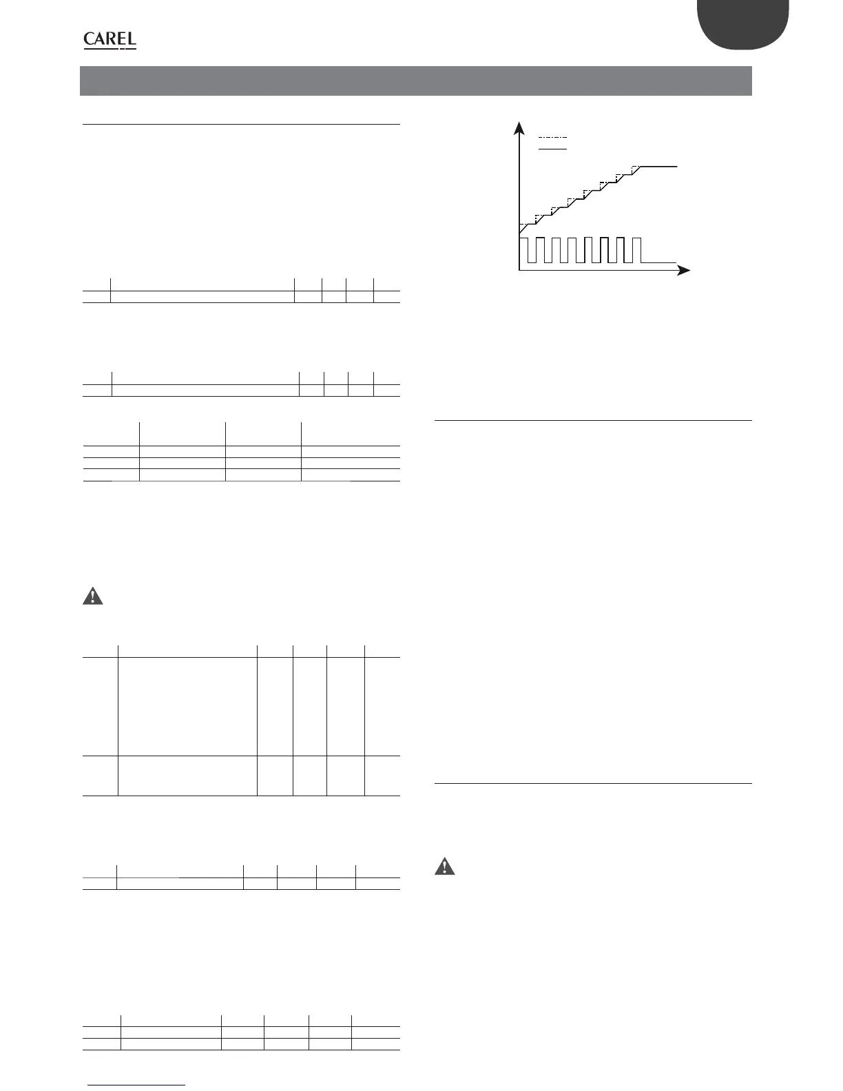
4.1.5 Soft start (parameter c57, d57)
This function is used to gradually increase or decrease the set point
according to the value of the parameter. The function is useful if the
controller is used in cold rooms or seasoning rooms, or in similar
situations when starting at full load may not be compatible with the
required process. Soft start, if active, is used on power-up or within an
operating cycle. The unit of measure is expressed in minutes / °C.
Parameter d57 acts on circuit 2 if independent operation is active.
Par. Description Def Min Max UoM
c57 Soft start 0 0 99 min/°C
d57 Soft start circuit 2 0 0 99
min/°C
Tab. 4.f
°C
set point
process value
output status
Fig. 4.a
Example: when c57=5, assuming the set point is 30°C and the di erential 2
°C, and that the ambient temperature is 20°C; on power-up the virtual set
point will be the same as the temperature measured, and will remain at this
value for 5 minutes. After 5 minutes, the virtual set point will be 21 degrees,
no outputs will be activated, while after another 5 minutes the virtual set
point will be 22°C, thus entering the control band (as the di erential is 2°C)
and heating will start. Once the temperature reaches the virtual set point,
the function stops and the process continues.
4.2 Preparing for operation
Once having completed the installation, con guration and programming
operations, before starting the controller check that:
• The wiring is performed correctly;
• The programming logic is suitable for controlling the unit and the
system being managed: Starting from revision FW 2.0 two PID control
cycles can be set on two independent circuits;
• If the controller is tted with RTC (clock), set the current time and the
on and o times;
• Set the standard display;
• Set the “probe type” parameter based on the probe available and the
type of control (NTC, NTC-HT, PTC, PT1000, J/K thermocouple, voltage/
current input);
• Set the type of control: ON/OFF (proportional) or proportional, integral,
derivative (PID);
• If used as a thermostat, set the unit of measure for the probes (°C or °F),
see paragraph 5.1;
• Any operating cycles are programmed correctly;
• The protection functions (delay at start-up, rotation, minimum on and
o times for the outputs) are active;
• The remote control enabling code is set, if a series of controllers are
installed in the same system;
• If the CONV0/10A0 module is connected, the cycle time is set to the
minimum (c12=0.2 s);
• The special mode is set in the correct sequence, i.e. rst parameter c0 is
set, and then parameter c33 (see the chapter on Functions).
4.3 Switching the controller On/O
The device can be switched ON/OFF from several sources: supervisor,
digital input (parameters c29, c30), parameter (Pon) and remote control.
The digital input has highest priority in switching ON/OFF. Staring
from revision 2.0 an output can be selected for ON-OFF status (see
“dependence”).
If more than one digital input is selected as On/O , the ON status will
be activated when all the digital inputs are closed. If just one contact
is open, the unit is switched OFF.
In OFF status set from digital input, the outputs and switching ON/OFF
from remote control or the supervisor are disabled, while the following
functions are enabled:
• editing and display of the frequent and con guration parameters, and
the set point;
• selection of the probe to be displayed;
• probe 1 error (E01), probe 2 error (E02), clock alarm (E06), EEPROM
alarm (E07 and E08);
• When switching ON and OFF the control output protection times are
taken into consideration;
 Loading...


