27
ENG
ir33 universale +030220801 - rel. 2.1 - 21.06.2011
5.2.1 Second probe (parameter c19)
Par. Description Def Min Max UoM
c19 Operation of probe 2
0=not enabled
1=di erential operation
2=compensation in cooling
3=compensation in heating
4=compensation always active
5=enable logic on absolute set point
6=enable logic on di . set point
7= independent op. (cir. 1+cir. 2)
8= control on higher probe value
9= control on lower probe value
10= control set point from B2
11= auto heat/cool change from B2
Validity c0= 1, 2, 3, 4
0011
-
Tab. 5.c
The second probe must be the same type as the rst, as set by
parameter c13. Nonetheless control can be performed on two
di erent physical values, for example temperature-humidity using
independent operation (c19=7) with combined active probe (e.g. CAREL
DPWC*) with two 4 to 20 mA outputs.
For the explanation of the types of control based on parameter c19, see
the chapter on “Control”.
5.3 Standard operating modes (parameters
St1,St2,c0,P1,P2,P3)
The controller can operate in 9 di erent modes, selected by parameter
c0. The basic modes are “direct” and “reverse”. In “direct” mode, the output
is activated if the value measured is greater than the set point plus a
di erential. In “reverse” mode the output is activated if the temperature is
less than the set point plus a di erential. The other modes are a combination
of these, with possibility of 2 set points (St1 & St2) and 2 di erentials (P1 &
P2) based on the mode, “direct” or “reverse”, or the status of digital input
1. Other modes include “dead zone” (P3), “PWM” and “alarm”. The number
of outputs activated depends on the model (V/W/Z=1,2,4 relay outputs,
A=4 SSR outputs, B/E=1/2 analogue outputs and 1/2 relay outputs).
Selecting the correct operating mode is the rst action to be performed
when the default con guration, i.e. “reverse” operation, is not suitable for
the application in question. For the description of “timer” operation see
paragraph 5.6.1 (dependence parameter=15)
Par. Description Def Min Max UoM
St1 Set point 1 20 c21 c22 °C (°F)
St2 Set point 2 40 c23 c24 °C (°F)
c0 1= direct
2= reverse
3= dead zone
4= PWM
5= alarm
6= direct/reverse from DI1
7= direct/direct from DI1
8= reverse/reverse from DI1
9= direct/reverse with separate set
point
219 -
P1 Set point di erential 1 2 0.1 50 °C (°F)
P2 Set point di erential 2 2 0.1 50 °C (°F)
P3 Dead zone di erential 2 0 20 °C (°F)
P1 Set point di erential 1 2 (3,6) 0.1(0,2) 99,9 (179) °C (°F)
P2 Set point di erential 2 2 (3,6) 0.1(0,2) 99,9 (179) °C (°F)
P3 Dead zone di erential 2 (3,6) 0 (0) 99,9 (179) °C (°F)
c21 Minimum value of set point 1 -50 -50 c22 °C (°F)
c22 Maximum value of set point 1 60 c21 150 °C (°F)
c21 Minimum value of set point 1 -50
(-58)
-199
(-199)
c22 °C (°F)
c22 Maximum value of set point 1 110
(230)
c21 800 (800) °C (°F)
c23 Minimum value of set point 2 -50 -50 c24 °C (°F)
c24 Maximum value of set point 2 60 c23 150 °C (°F)
c23 Minimum value of set point 2 -50
(-58)
-199
(-199)
c24 °C (°F)
c24 Maximum value of set point 2 110
(230)
c23 800 (800) °C (°F)
Tab. 5.d
To be able to set c0, the value of c33 must be 0. If c33=1, changing c0
has no e ect.
For the mode set to become immediately operational, the controller
needs to be switched o an on again. Otherwise correct operation is
not guaranteed.
The meaning of parameters P1 & P2 changes according to the
operating mode selected. Fore example, in modes 1 & 2 the
di erential is always P1. P2, on the other hand, is the “reverse” di erential
in mode 6 and the “direct” di erential in mode 9.
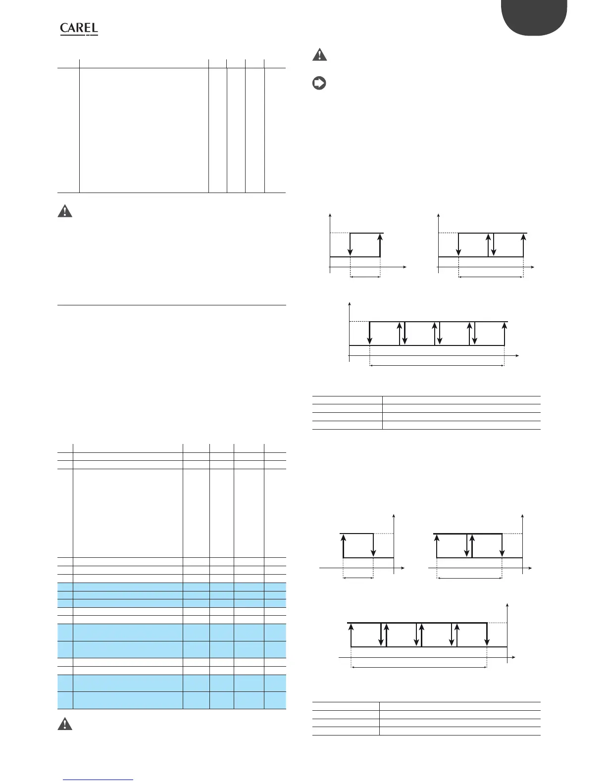
5.3.1 Mode 1: Direct c0=1
In “direct” operation the controller ensures the value being controlled (in
this case the temperature) does not exceed the set point (St1). If it does,
the outputs are activated in sequence. The activation of the outputs is
distributed equally across the di erential (P1). When the value measured
is greater than or equal to St1+P1 (in proportional only operation), all the
outputs are activated. Similarly, if the value measured starts falling, the
outputs are deactivated in sequence. When reaching St1, all the outputs
are deactivated.
ON
OUT1
Mod. V
OFF
St1
B1P1
ON
OUT1 OUT2
Mod. W
OFF
St1
B1
P1
ON
OUT1 OUT2OUT3OUT4
Mod. Z
OFF
St1
B1
P1
Fig. 5.c
Key
St1 Set point 1
P1 Set point di erential 1
OUT1/2/3/4 Output 1/2/3/4
B1 Probe 1
5.3.2 Mode 2: Reverse c0=2 (Default)
“Reverse” operation is similar to ”direct” operation, however the outputs
are activated when the value being controlled decreases, starting from
the set point (St1). When the value measured is less than or equal to
St1-P1 (in proportional only operation), all the outputs are activated.
Similarly, if the value measured starts rising, the outputs are deactivated
in sequence. When reaching St1, all the outputs are deactivated.
ON
OUT1
Mod. V
OFF
ON
OFF
St1
B1P1
OUT1OUT2
Mod. W
St1
B1
P1
ON
OUT1OUT2OUT3OUT4
Mod. Z
OFF
St1
B1
P1
Fig. 5.d
Key
St1 Set point 1
P1 Set point di erential 1
OUT1/2/3/4 Output 1/2/3/4
B1 Probe 1
 Loading...


