23
ENG
ir33 universale +030220801 - rel. 2.1 - 21.06.2011
3.4.11 Displaying the inputs
• Press : the current input will be displayed, alternating with the
value:
b1 : probe 1;
b2 : probe 2;
di1 : digital input 1;
di2 : digital input 2.
St1 : set point 1;
St2 : set point 2.
Fig. 3.o
Fig. 3.p
• Press and to select the input to be displayed;
• Press Set for 3 seconds to con rm.
If when scanning the inputs a digital input has not been con gured,
the display will show “nO” (indicating that the digital input does not
exist or has not been con gured), while “OPn” and “CLO” will be displayed to
indicate, respectively, that the input is open or closed. For the probes, the
value displayed will be the value currently measured by the probe or, if the
probe is not tted or not con gured, the display will show “nO”.
For St2, this is only displayed if featured on the controller, otherwise the
display shows ”nO”.
3.4.12 Calibrating the probes
Parameters P14 and P15 are used to calibrate the rst and second
probe respectively. See paragraph 5.2 for the di erence in calibration
between temperature probes and current and voltage inputs. Access
the 2 parameters and then set the required values. When pressing Set,
after having entered the value, the display does not show the parameter,
but rather immediately shows the new value of the probe reading
being calibrated. This means the result of the setting can be checked
immediately and any adjustments made as a consequence. Press Set
again to save the value.
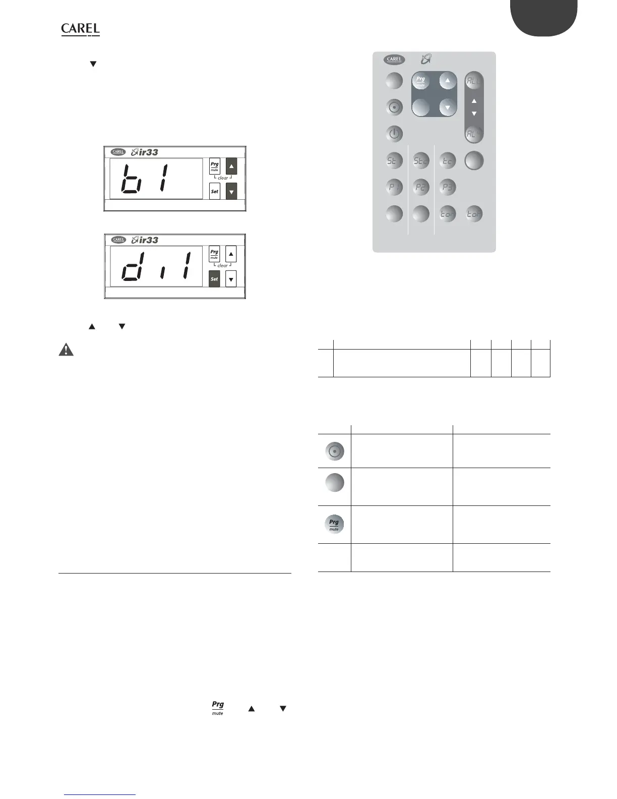
3.5 Using the remote control (accessory)
The compact remote control with 20 buttons allows direct access to the
following parameters:
• St1 (set point 1)
• St2 (set point 2)
• P1 (di erential St1)
• P2 (di erential St2)
• P3 (dead zone di erential)
and the following functions can also be accessed:
• set the time
• display the value measured by the probes
• display the alarm queue and reset any alarms with manual reset, once
the cause has been resolved.
• set the on time band (see the corresponding paragraph).
The remote control features the four buttons,
, Set, and ,
which access almost all the functions provided by the instrument keypad.
The buttons can be divided into three groups, based on their functions:
• Enabling/disabling the use of the remote control (Fig. 1);
• Remote simulation of the controller keypad (Fig. 2);
• Direct display/editing of the most common parameters (Fig. 3).
Set
3
456
12
7890
Set point 1 Set point 2
Dead zone
Diff 1 Diff 2
Time ON Time OFF
Clock
remote control
product part number IRTRUES000
Alarm
Probe 2Probe 1
Reset
Esc
Fig. 3.q
3.5.1 Remote control enable code (parameter c51)
Parameter c51 attributes a code for accessing the controller. This means
that the remote control can be used when there are a series of controllers
on the same panel, without the risk of interference.
Par. Description Def Min Max UM
c51
Code for enabling the remote control
0=Programming by remote control
without code
1 0 255 -
Tab. 3.d
3.5.2 Activating and deactivating the use of the
remote control
Button Immediate function Delayed function
used to enable the remote
control; each instrument
displays its own enabling code
Esc
ends operation using the
remote control, cancelling
all changes made to the
parameters
pressing and holding for 5s
ends the operation of the
remote control, saving the
modi ed parameters
NUMS.
used to select the instrument,
by entering the enabling code
displayed.
 Loading...


