24
ENG
ir33 universale +030220801 - rel. 2.1 - 21.06.2011
Fig. 3.r
The buttons used are shown in the gure. By pressing the
button,
each instrument displays its own remote control enabling code
(parameter c51). The numeric keypad is used to enter the enabling code
of the instrument in question. At the end of this operation, only the
instrument with the selected enabling code will be programmed from
the remote control, all the others will resume normal operation. Assigning
di erent enabling codes to the instruments, allows, in this phase, only the
desired instrument to be programmed using the remote control, without
the risk of interference. The instrument enabled for programming from
the remote control will display the reading and the message rCt. This
status is called Level 0. Press
Esc
to exit the programming of the remote
control, without saving the modi cations.
3.5.3 Remote simulation of the controller keypad
The buttons used are shown in the gure. In Level 0 (display the reading
and message rCt), the following functions are active:
Button Immediate function
Mute the buzzer, if ON
In this level, the Set and buttons are also active, used to activate the set
point (Level 1) and the con guration parameters (Level 2).
Button Immediate function Delayed function
Pressing and holding for 5s saves
the modi ed parameters and ends
the operation of the remote control
Set
Set the set point
In Levels 1 and Level 2, the
, Set, and buttons repeat the
corresponding functions on the controller keypad. In this way, all the
controller parameters can be displayed and set, even those without
shortcut buttons.
Set
remote control
Fig. 3.s
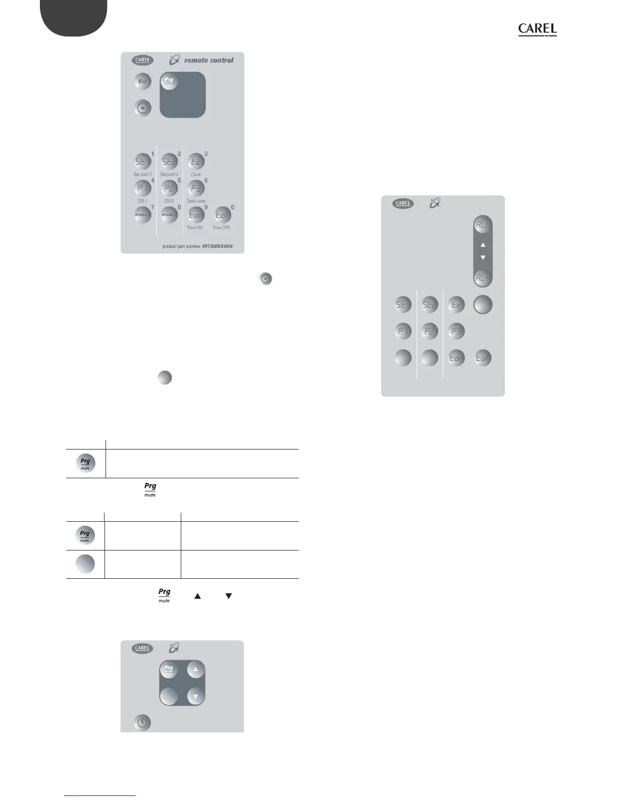
3.5.4 Direct display/editing of the most common
parameters
Some parameters are directly accessible using speci c buttons:
• St1 ( set point 1);
• St2 ( set point 2);
• P1 (di erential St1);
• P2 (di erential St2);
• P3 (dead zone di erential)
and the following functions can also be accessed:
• set the current time(tc);
• display the value measured by the probes (Probe1, Probe2);
• display the alarm queue (AL0-AL4);
• reset any alarms with manual reset, once the cause has been resolved;
• set the on time band ( ton, toF), see the corresponding paragraph.
3
456
12
7890
Set point 1 Set point 2
Dead zone
Diff 1 Diff 2
Time ON Time OFF
Clock
remote control
product part number IRTRUES000
Alarm
Probe 2Probe 1
Reset
Fig. 3.t
 Loading...


