8
ENG
ir33 universale +030220801 - rel. 2.1 - 21.06.2011
1.2 Functions and main characteristics
The IR33/DN33 controllers feature two main types of operation: “direct”
and “reverse”, based on the value measured. In “direct” operation, the
output is activated if the value measured exceeds the set point plus
a di erential, and thus aims to keep the value below a certain level
(typically used in refrigeration systems). Vice-versa, in “reverse” operation
the output is activated when the temperature falls below the set point
plus a di erential (typically used in heating systems).
There are nine preset operating modes in which the installer can choose
the set point and the activation di erential.
In “special” operating mode, the exact activation point and deactivation
and the control logic, “direct” or “reverse”, can both be set, guaranteeing
signi cant exibility. Finally, automatic cycles can be programmed, called
“operating cycles”, used for example in processes where the temperature
must remain above a certain value for a minimum time (pasteurisation). An
operating cycle is de ned by ve time intervals in which the temperature
must reach a certain set point. The operating cycle is activated on the
keypad, via digital input or automatically on the models with RTC. On
all models, it runs for the set time , thanks to the internal timer. The
remote control, an accessory available for all the controllers, has the same
buttons as the controller interface, and in addition can directly display the
most frequently used parameters. Based on the model of controller, the
output activated may be a relay, a PWM signal for solid state relays (SSR)
or a voltage that increases linearly from 0 to 10 Vdc. The PWM output can
also be converted, using the following modules:
• CONV0/10A0: conversion from PWM output for SSR to a linear 0 to 10
Vdc or 4 to 20 mA analogue signal;
• CONONOFF0: conversion from PWM output for SSR to an ON/OFF relay
output.
Starting rmware revision 2.0, IR33 Universale can manage two circuits
with independent PID control. New software functions have also been
introduced, such as speed-up, cut-o and forcing the output from
digital input, which can be selected for each output. See the paragraph
“Software revisions” and the chapter “Functions”.
Below is a description of the accessories for the IR33/DN33 Universal:
ComTool programming tool
(downloadable from http://ksa.carel.com)
With this useful tool, the controller can be programmed from any PC,
saving the di erent con gurations to les that can be loaded during the
nal programming stage, creating custom sets of parameters for faster
programming and setting di erent user pro les with access protected
by password.
The PC must be tted with the USB/RS485 converter (CVSTDUMOR0) and
the RS485 serial interface (IROPZ48500).
Fig. 1.a
Remote control (cod. IRTRUES000)
Used to directly access the main functions, the main con guration
parameters and to program the controller from a distance, using a group
of buttons that exactly replicate the keypad on the controller.
Set
3
456
12
7890
Set point 1 Set point 2
Dead zone
Diff 1 Diff 2
Time ON Time OFF
Clock
remote control
product part number IRTRUES000
Alarm
Probe 2Probe 1
Reset
Esc
Fig. 1.b
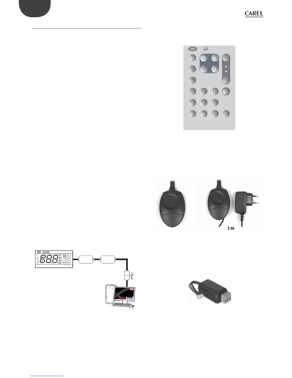
Programming key (code IROPZKEY00) and programming key with
power supply (code IROPZKEYA0)
The keys can be used to quickly program the controllers, even when
not connected to the powered supply, reducing the risk of errors. These
accessories also allow fast and e ective technical service, and can be
used for programming the controllers in just a few seconds, also during
the testing phase.
Fig. 1.c
RS485 serial interface (code IROPZ48500 & IROPZ485S0)
These t directly into the connector that normally is used for programming
via key, and allow connection to the PlantVisor supervisory system. These
options have been designed to remain outside of the controller and
consequently the connection to the PlantVisor supervisory system can
be installed at any time, even subsequently, if the system requires. Model
IROPZ485S0 features a microprocessor and can automatically recognise
the TxRx+ and TxRx- signals (possibility to reverse the connection).
Fig. 1.d
 Loading...


