38
ENG
ir33 universale +030220801 - rel. 2.1 - 21.06.2011
Par. Description Def Min Max UoM
P70
Enable working cycle
0=Disabled
1=Keypad
2=Digital input
3=RTC
00 3 -
P71
Working cycle: step 1 duration
0 0 200 min
P72
Working cycle: step 1 temperature set
point
0 (32) -50
(-58)
150
(302)
°C(°F)
P72
Working cycle: step 1 temperature set
point
0 (32) -199
(-199)
800(800) °C(°F)
P73
Working cycle: step 2 duration
0 0 200 min
P74
Working cycle: step 2 temperature set
point
0 (32) -50
(-58)
150
(302)
°C(°F)
P74
Working cycle: step 2 temperature set
point
0 (32) -199
(-199)
800(800) °C(°F)
P75
Working cycle: step 3 duration
0 0 200 min
P76
Working cycle: step 3 temperature set
point
0 (32) -50
(-58)
150
(302)
°C(°F)
P76
Working cycle: step 3 temperature set
point
0 (32) -199
(-199)
800(800) °C(°F)
P77
Working cycle: step 4 duration
0 0 200 min
P78
Working cycle: step 4 temperature set
point
0 (32) -50
(-58)
150
(302)
°C(°F)
P78
Working cycle: step 4 temperature set
point
0 (32) -199
(-199)
800(800) °C(°F)
P79
Working cycle: step 5 duration
0 0 200 min
P80
Working cycle: step 5 temperature set
point
0 (32) -50
(-58)
150
(302)
°C(°F)
P80
Working cycle: step 5 temperature set
point
0 (32) -199
(-199)
800(800) °C(°F)
Tab. 6.d
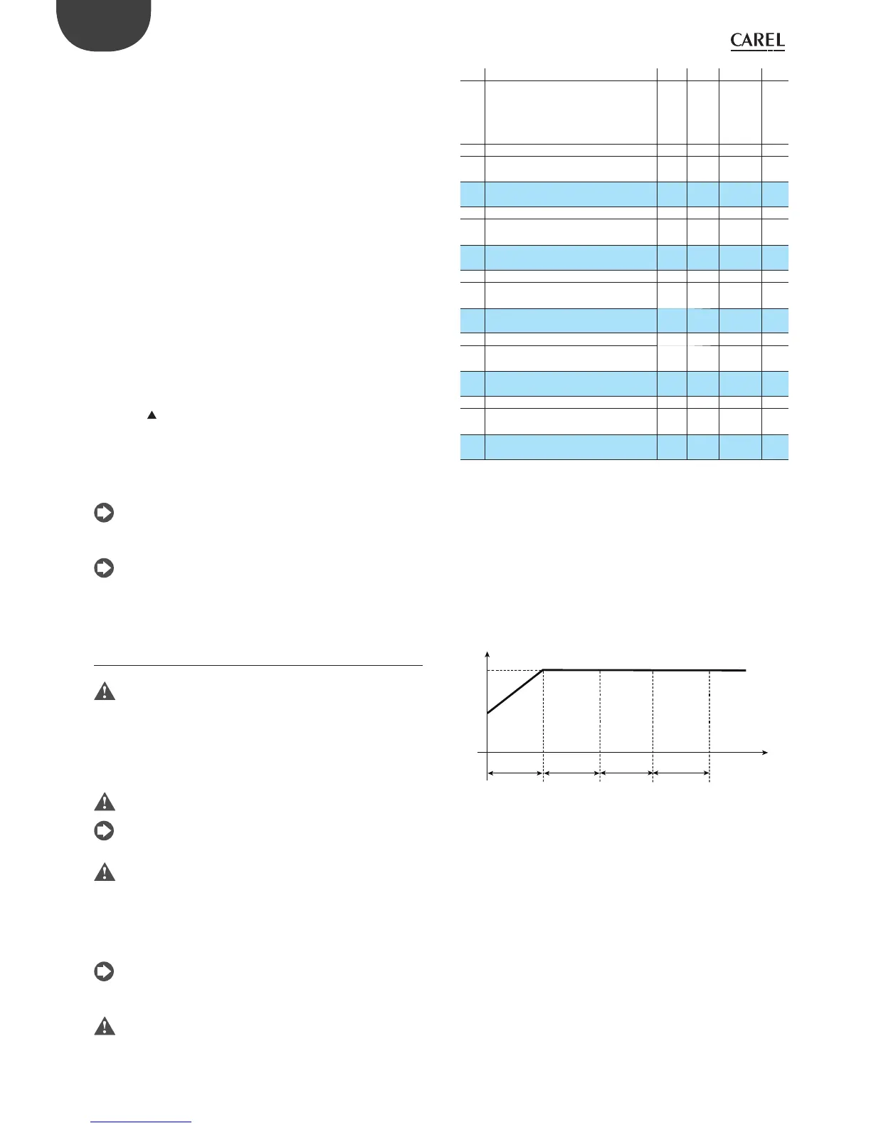
Example 1: Heating cycle with in nite temperature control
In this example, Step1 is used to bring the system to the temperature
SetA, while the next step ensures in nite temperature control. In this
case only 2 steps would be needed, however the cycle requires the
Temperature and Time parameters to be set for all of the steps. For this
reason, Steps 2, 3 and 4 are set to the control temperature SetA for a time
of 1 (this could in any case be set to the maximum value available, being
in nite temperature control), while for the fth and nal step the time is
set to “0”. This means the operating cycle will not stop unless the operator
intervenes.
t
T
STEP1
P71=45’
P72=SetA
STEP2
P73=1
P74=SetA
SetA
1’45’
1’ 1’
STEP3
P75=1
P76=SetA
STEP4
P77=1
P78=SetA
STEP5
P79=0
P80=SetA
Fig. 6.a
current state of the system, introducing alterations that when measured
are used to calculate the most suitable PID parameters for the system in
question. In this phase, the temperature reached by the unit may di er
considerably from the set point, and may also return to the starting value.
At the end of the process (maximum duration of 8 hours), if the outcome
is positive, the values calculated for the control parameters will be saved
and will replace the default value, otherwise nothing will be saved and
the controller will signal an alarm (see the table of alarms), and exit the
procedure. In these cases, the signal remains until manually reset or the
controller is switched o and on again, while the Auto-Tuning procedure
will in any case be terminated and the parameters will not be modi ed.
Fine-tuning the controller with parameters that have already been
tuned, during normal operation.
If the controller has already been tuned a rst time, the Auto-Tuning
procedure can be repeated to further tune the values. This is useful when
the loads have changed since the rst procedure was performed, or to
allow ner tuning. The controller in this case can manage the system
using the PID parameters, and further Auto-Tuning will have the e ect
of improving control.
This time, the procedure can be started during normal control of the
system (with c0 =1 or 2, that is, control in “direct” or “reverse” mode, and c5
=1, that is, PID control enabled); the controller in this case does not need
to be switched o and on again; simply:
-set parameter c64 to 1;
-press the
button for 5 seconds, after which the unit will display the
message “tun” and Auto-Tuning will start.
The controller then proceeds with Auto-Tuning as already described
above. In both modes described, if the procedure ends positively, the
controller will automatically set parameter c64 to zero and will activate
PID control with the new parameters saved.
The Auto-Tuning procedure should not be considered essential in
achieving optimum control of the system; experienced users can
also achieve excellent results by setting the parameters manually.
For users experienced in operating the IR32 Universal family
controllers in P+I mode, simply set c5=1 (that is, PID control enabled)
and use the default values of the parameters, thus replicating the
behaviour of the previous model of controller.
6.4 Operating cycle
The operating cycle function is incompatible with independent
operation (c19=7).
The operating cycle is an automatic program that can have a maximum
of 5 set points to be reached in the 5 respective time intervals. This may
be useful for automating processes in which the temperature must follow
a set pro le for a certain time (e.g. milk pasteurisation).
The duration and temperature must be set for all 5 steps.
The operating cycle is started from the keypad, digital input or
automatically by RTC. See the chapter on the “User interface”.
If the duration of step x, (P73, P75, P77, P79) is set a zero, it means that
the controller only manages the temperature. The controller will try
to reach the set temperature in the shortest possible time, after which it
will go to the next step. On the contrary, P71 must be set ≠ 0. With
duration of the step ≠ 0, the controller will try to reach the set temperature
in the established time, and then anyway it will go on to the next step.
If during a operating cycle the unit is switched OFF, control stops
however the step continues to be counted. Once the unit is started
again (ON), control resumes.
The operating cycle is stopped automatically in the event of a probe
fault or error from digital input.
 Loading...


