33
ENG
ir33 universale +030220801 - rel. 2.1 - 21.06.2011
only be activated after the activation of output ‘x’. The output with the
activation restriction set to 0 will be activated irrespective of the other
outputs.
5.6.6 Deactivation restriction (par. d35,d39,d43,d47)
In normal operating conditions, the deactivation sequence should be as
follows: 4,3,2,1. However, due to minimum on/o times or times between
successive activations, the sequence may not be observed. By setting
this restriction, the correct sequence is observed even when timers have
been set. The output with the deactivation restriction set to ‘x’ (1,2,3) will
only be deactivated after the deactivation of output ‘x’. The output with
the deactivation restriction set to 0 will be deactivated irrespective of the
other outputs.
5.6.7 Minimum modulating output value
(parameters d36,d40,d44,d48)
Valid if the output is the control output and the “type of output”=1, that
is, the output is PWM or in case of 0 to 10Vdc output. The modulating
output can be limited to a relative minimum value.
Example of proportional control: “reverse” mode with St1 =20°C and
P1=1°C. If only one modulating output is used with a di erential of 1°C,
setting this parameter to 20 (20%) will mean the output is only activated
when the temperature measured deviates more than 20% of the set
point, that is, with values less than 19.8°C as shown in the gure.
100%
OUT1
0%
d36=20%
St1
B1
P1
Fig. 5.q
Key
St1 Set point 1 P1 “Reverse” di erential
OUT1 Output 1 d36 Min. value of modulating output 1
B1 Probe 1
5.6.8 Maximum modulating output value
(parameters d37,d41,d45,d49)
Valid if the output is the control output and the “type of output”=1, that
is, the output is PWM or in case of 0 to 10Vdc output. The modulating
output can be limited to a relative maximum value.
Example of proportional control: “reverse” mode with St1 =20°C and
P1=1°C. If only one modulating output is used with a di erential of 1°C,
setting this parameter to 80 (80%) will mean the output is only activated
when the temperature measured deviates more than 80% of the set
point, that is, with values less than 19.2°C. After this value the output will
remain constant, as shown in the gure.
100%
OUT1
0%
d37=80%
St1
B1
P1
Fig. 5.r
Key
St1 Set point 1
P1 “Reverse” di erential
d37 Maximum value of modulating output 1
OUT1 Output 1
B1 Probe 1
5.6.9 Modulating output cut-o
(parameters F34,F38, F42, F46)
These parameters are useful when needing to apply a minimum voltage
value for operation of an actuator.
They enable operation with a minimum limit for the PWM ramp and 0 to
10 Vdc analogue output.
Example: control with two outputs, the rst(OUT1) ON/OFF and the
second (OUT2) 0 to 10 Vdc;
“minimum value of the modulating output” for output 2= 50 (50% of the
output), d40=50.
CASE 1 : F38 = 0 Cut o operation
100%
0%
d40=50%
St1
B1
P1
P1/2
P1/2
OUT2 OUT1
c0=2
Fig. 5.s
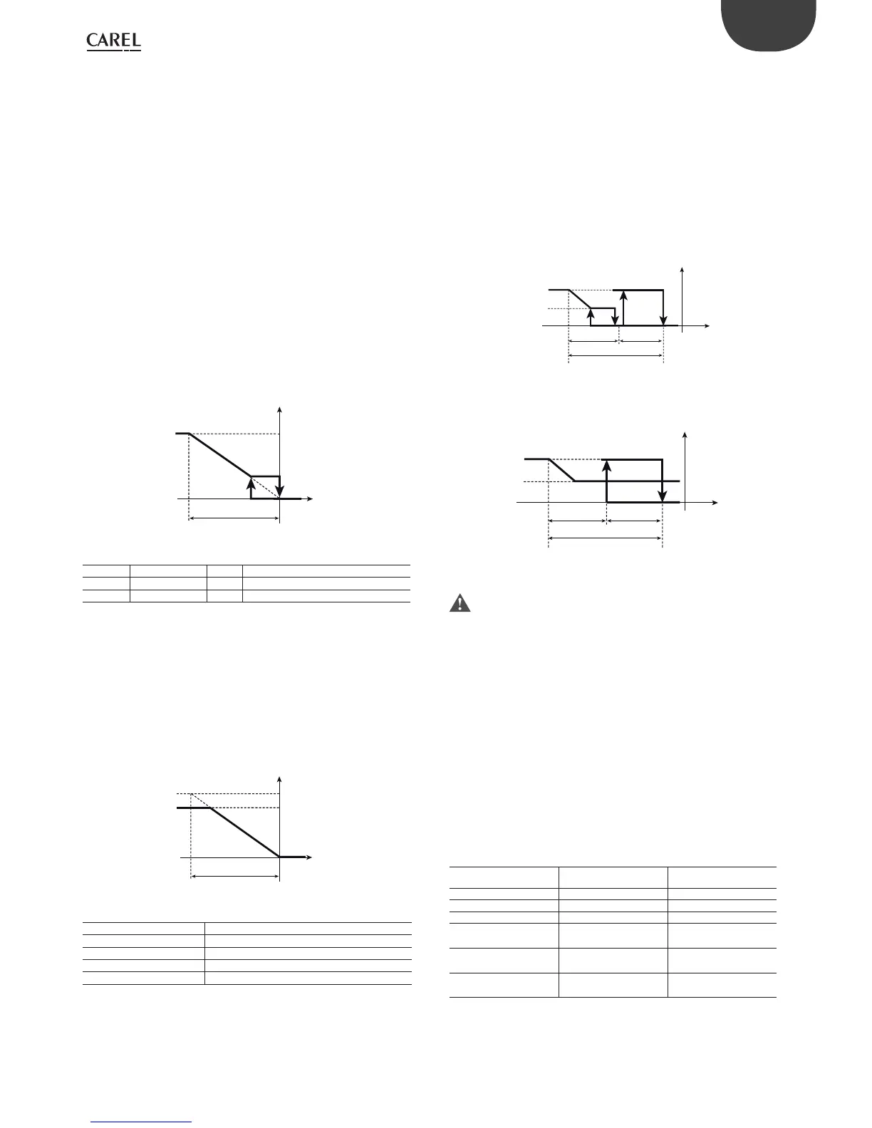
CASE 2 : F38 = 1 Minimum speed operation
100%
0%
d40=50%
St1
B1
P1
P1/2
P1/2
OUT2 OUT1
c0=2
Fig. 5.t
When modulating output cut-o is enabled, the on (d34, d38, d42,
d46) and o limits (d35, d39, d43, d47) must be set correctly.
5.6.10 Modulating output speed up time
(parameters F35, F39, F43, F47)
These parameters are used to activate the modulating output to the
maximum value allowed (parameters d37, d41, d45, d49) for a set time,
starting from the instant the output is activated. Setting it to 0 disables
the speed up function.
5.6.11 Override outputs
(parameters F36, F40, F44, F48)
These parameters determine how the relay or modulating control output
is overridden, activated by digital input (c29=6, c30=6).
The e ect on the output depends on whether the output is a relay or
modulating.
Override output action
TYPE OF OVERRIDE RELAY OUTPUT MODULATING OUTPUT
0 - -
1 OFF respecting c6, c7 0%, 0 Vdc
2 ON 100%, 10 Vdc
3 - minimum set (d36, d40,
d44, d48)
4 - maximum set (d37, d41,
d45, d49)
5 OFF respecting c6,
c7,d1, c8, c9
-
Tab. 5.l
 Loading...


