32
ENG
ir33 universale +030220801 - rel. 2.1 - 21.06.2011
The “activation” parameter is expressed as a percentage, from -100 to +100
and refers to the operating di erential and the set point that the output
refers to. If the output refers to St1 (“dependence”=1), “activation” is relative
to the percentage value of P1; if the output refers to St2 (“dependence”= 2),
“activation” is relative to the percentage value of P2.
If the value of “activation” is positive, the activation point is to the ‘right’ of the
set point, while if negative it is to the ‘left’.
If “dependence”=15 & “type of output”=1, the “activation” parameter
de nes the ON time as a percentage of the period (c12); in this case, “
activation” must only have positive values (1 to 100).
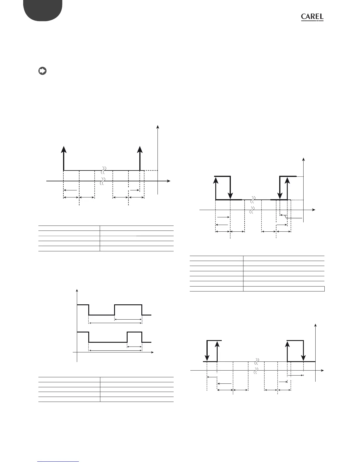
Example 1:
The gure below shows the activation points on a controller with 2
outputs, with the following parameters:
St1=10, St2=20, P1=P2=6
OUT1 (point A): “dependence”=c34=1, “activation”= c36=-100;
OUT2 (point B): “dependence”=c38=2, “activation”= c40= +75.
A=4; B=24.5
St1=10
c36=-100
St2=20
c40=+75
OUT1
AB
OUT2
B1
P1=6 P1=6 P2=6 P2=6
ON
OFF
Fig. 5.m
Key
St1/2 Set point 1/2
P1 Di erential for output 1
P2 Di erential for output 2
OUT1/2 Output 1/2
B1 Probe 1
Example 2
A “timer” output is selected with “dependence”=15, “type of output”=1
and “activation” (ON percentage) between 1 and 100, with a cycle time
set by c12. Below OUT1 and OUT2 are proposed as “timer” outputs with
c36 greater than c40, example:
OUT1: c34=15, c35=1, c36=50; OUT2: c38=15, c39=1, c40=25.
ON
OUT1
OUT2
OFF
t
c12
TON_2
ON
OFF
c12
TON_1
Fig. 5.n
Key
t time
c12 cycle time
OUT1/2 Output 1/2
TON_1 (c36*c12)/100
TON_2 (c40*c12)/100
5.6.4 Di erential/logic ( parameters c37,c41,c45,c49)
The “di erential/logic” parameter is only active if the output is the control
output (“dependence”=1,2,16,17). Like the “activation” parameter, it is
expressed as a percentage and is used to de ne the hysteresis of the
output, that is, for ON/OFF operation, the deactivation point of the output
or, for PWM operation, the point where the output has the minimum value
(ON time =0). If the output refers to St1 (“dependence”=1), “di erential/
logic” is relative to the percentage value of P1; if the output refers to St2
(“dependence”= 2), “di erential/logic” is relative to the percentage value
of P2. If the value of “di erential/logic” is positive, the deactivation point is
greater than the activation point and “reverse” logic is created.
If the value of “di erential/logic” is negative, the deactivation point is less
than the activation point and “direct” logic is created.
Together with the previous “activation” parameter, this identi es the
proportional control band.
Example 3.
Example 3 completes example 1, adding the deactivation points.
For the rst output “reverse” operation is required, and the di erential P1;
for the second, “direct” logic and the di erential equal to half of P2.
The parameters are :
Output 1 : “di erential/logic”=c37=+100 (A’)
Output 2: ”di erential/logic”=c41=-50 (B’)
A’=10; B’=21.5
c36=-100
c37=+100
c41=-50
c40=+75
OUT1
AA’ B’B
OUT2
B1
P1=6 P1=6 P2=6 P2=6
St1=10 St2=20
ON
OFF
Fig. 5.o
Key
St1/2 Set point 1/2
c36/c40 Activation of output 1/2
c37/c41 Di erential/logic for output 1/2
OUT1/2 Output 1/2
P1 Set point di erential 1
P2 Set point di erential 2
B1 Probe 1
As an example, reversing the values of “di erential/logic”, the new
deactivation points are as follows
Output 1 : “di erential/logic”=c37=-50(A’)
Output 2: ”di erential/logic”=c41=+100 (B’)
A’’=1; B’’=30.5
c36=-100
OUT1
A’’ A B
B’’
OUT2
B1
P1=6 P1=6 P2=6 P2=6
St1=10 St2=20
ON
OFF
c40=+75
c41=+100
c37=-50
Fig. 5.p
5.6.5 Activation restriction (par. d34,d38,d42,d46)
In normal operating conditions, the activation sequence should be as
follows: 1,2,3,4. However, due to minimum on/o times or times between
successive activations, the sequence may not be observed. By setting
this restriction, the correct sequence is observed even when timers have
been set. The output with the activation restriction set to ‘x’ (1,2,3) will
 Loading...


