43
ENG
ir33 universale +030220801 - rel. 2.1 - 21.06.2011
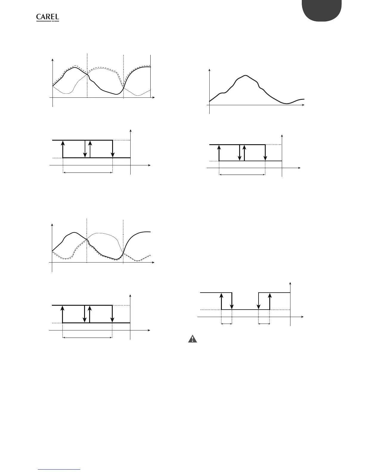
6.5.8 Control on higher/lower probe value
(parameter c19=8/9)
Setting c19=8, the probe used by the controller to activate control and
consequently the outputs is whichever probe measures the higher value.
t
T
Control by
B2
Control by
B1
Control by
B1
B1
B2
OFF
P1
St1
max(B1,B2)
ON
OUT1OUT2
OFF
c0=2
c19=8
Mod. W
Fig. 6.q
Key
T= temperature
t= time
Setting c19=9, the probe used by the controller to activate control and
consequently the outputs is whichever probe measures the lower value.
t
T
Control by
B1
Control by
B2
Control by
B2
OFF
P1
St1
min(B1,B2)
ON
OUT1OUT2
OFF
c0=2
c19=9
Mod. W
B1
B2
Fig. 6.r
Key:
T= temperature
t = time
6.5.9 Control set point set from probe 2 (parameter
c19=10)
The control set point is no longer xed, but rather varies based on the
value of probe B2. For current or voltage inputs, St1 will not be the voltage
or current value, but rather the value shown on the display, depending
on parameters d15 and d16.
t
St1
B2
P1
St1=B2
B1
ON
OUT1OUT2
OFF
c0=2
c19=10
Mod. W
Fig. 6.s
Key:
T= temperature
t= time
6.5.10 Heat/cool changeover from probe B2
(parameter c19=11)
When c19=11, if the value of probe B2 within the interval de ned by c66
and c67, the controller remains in standby. When the value of probe B2
is less than C66, control is performed based on the parameters set by the
user; while when the value of probe B2 is higher than c67, the set point,
band and control logic are changed automatically.
One typical example is the changeover in operation of the fan coil based
on the supply water temperature.
c19=11
c0=1
c65
c67
c66
c65
B2
ON
OFF
Standby Heating
(St2, P2)
Cooling
(St1, P1)
Fig. 6.t
Do not use this function in combination with dependency settings
16 and 17.
6.5.11 Using the CONV0/10A0 module (accessory)
This module converts a 0 to 12 Vdc PWM signal for solid state relays to a linear
0 to 10 Vdc and 4 to 20 mA analogue signal.
Programming: to get the modulating output signal, the PWM control mode is
used (see the explanation for parameter c12). The PWM signal is reproduced
exactly as an analogue signal: the percentage ON time corresponds to the
percentage of the maximum output signal. The optional CONV0/10A0
module integrates the signal provided by the controller: the cycle time
(c12) must be reduced to the minimum value available, that is, c12=0.2 s.
As concerns the control logic (“direct”=cooling, “reverse”=heating), the same
observations seen for PWM operation apply (see mode 4): the PWM activation
logic is faithfully reproduced as an analogue signal. If, on the other hand, a
custom con guration is required, refer to the paragraphs on special operation
(“type of output”, ”activation”, “di erential/logic” parameters).
 Loading...


