55
ENG
ir33 universale +030220801 - rel. 2.1 - 21.06.2011
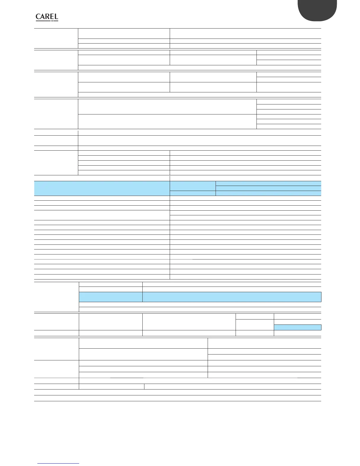
Maximum load on
individual relay
DN33x(V,W,Z,B,E)x(H,M)x(B,R)20
IR33x(V,B)x(H,M)x(B,R)20
8A
IR33x(W,E)x(H,M)x(B,R)20 4A
IR33Zx(H,M)x(B,R)20 2A
SSR outputs model Max output voltage: 12 Vdc
IR33Ax(7, 9)x(L, M)R20 - DN33Ax(7, 9)x(L, M)R20
IR33Ax(7, 9)Hx(R,B)20 - DN33Ax(7, 9)Hx(R,B)20
A = 4 SSR outputs Output resistance: 600
Output current max: 20 mA
maximum length of cables less than 10 m
0 to 10 Vdc outputs IR33Bx(7, 9)x(L, M)R20
DN33Bx(7, 9)x(L, M)R20
B = 1 Relay + 1 0 to 10 Vdc Typical ramp time (10 to 90%): 1 s
Max output ripple: 100 mV
IR33Ex(7, 9)Hx(R,B)20
DN33Ex(7, 9)Hx(R,B)20
E = 2 Relays + 2 0 to 10 Vdc Max output current: 5 mA
maximum length of cables less than 10 m
Insulation guaranteed
by the outputs
insulation from extra low voltage parts/insulation between relay outputs D01, D03 and 0 to 10 Vdc
outputs (relay outputs A02, A04)
reinforced
6 mm clearance, 8 mm creepage
3750 V insulation
insulation between outputs basic
3 mm clearance, 4 mm creepage
1250 V insulation
IR receiver On all models
Clock with backup
battery
IR33x(V,W,Z,A,B,E)x(7, 9)HB20, DN33x(V,W,Z,A,B,E)x(7, 9)HB20
Buzzer available on all models
Clock error at 25°C ± 10 ppm (±5.3 min/year)
Error in range -10T60°C -50 ppm(±27 min/year)
Ageing < ±5 ppm (±2.7 min/year)
Discharge time 6 months typical (8 months maximum)
Recharge time 5 hours typical (< 8 hours maximum)
Operating temperature -10T60 °C
Operating temperature
-10T55 °C DN33x(V,W,Z,A,B,E)9x(H,M)x(B,R)20
IR33x(V,W,Z,A,B,E)9MR20
-10T50 °C IR33x(V,W,Z,A,B,E)9Hx(B,R)20
Operating humidity <90% U.R. non-condensing
Storage temperature -20T70 °C
Storage humidity <90% U.R. non-condensing
Front panel index of protection IR33: assembly on smooth and indeformable panel with IP65 gasket
DN33: front panel IP40, complete controller IP10
Construction of control device Integrated electronic control device
Environmental pollution 2 normal
PTI of the insulating materials Printed circuits 250, plastic and insulating materials 175
Period of stress across the insulating parts Long
Class of protection against voltage surges Category 2
Type of action and disconnection 1.C relay contacts (microswitching)
Classi cation according to protection against electric shock Class 2 when appropriately integrated
Device designed to be hand-held or integrated in hand-held devices No
Software class and structure Class A
Front panel cleaning Only use neutral detergents and water
Carel serial network interface External, available on all models
Programming key Available on all models
Connections model
temperature inputs only Plug-in, for 0.5 to 2.5 mm2 cables, max current 12 A
universal inputs Plug-in, power supply and outputs for 0.5 to 2.5 mm
2
cables
Digital and analogue inputs for 0.2 to 1.5 mm
2
cables
Correct sizing of the power and connection cables between the controller and the loads is the responsibility of the installer.
In the max load and max operating temp. conditions, the cables used must be suitable for operation up to 105°C.
Case plastic IR33 (panel) frontal dimensions 76,2x34,2 mm
mounting depth 75 mm
93 mm
DN33 (DIN rail) dimensions 70x110x60
Assembly IR33: on smooth and indeformable panel
DN33: DIN rail
IR33: side fastening brackets, to be pressed in fully
drilling template IR33: 71x29 mm
DN33: 4 DIN modules
Display digits 3 digit LED
display –199 to 999
operating status indicated with graphic icons on the display
Keypad 4 silicone rubber buttons
Ball Pressure Test IR33x(V,W,Z,A,B,E)9x(H,M)x(B,R)20 85°C for accessible parts - 125°C for parts that carry live current
Outputs (0 to 10 Vdc, SSR, probe power supply) and inputs (probes and digital) are extra low voltage (not SELV)
Models DN33A9x(H,M)x(B,R)20 and IR33A9x(H,M)x(B,R)20 are not compliant with IEC EN 55014-1
Tab. 9.a
In the table of technical speci cations, the highlighted values represent the di erence between the models with universal inputs and the models with temperature
inputs only.
**) Relay not suitable for uorescent loads (neon lights, etc.) that use starters (ballasts) with phase shifting capacitors. Fluorescent lamps with electronic controllers or
without phase shifting capacitors can be used, depending on the operating limits speci ed for each type of relay.
 Loading...


