13
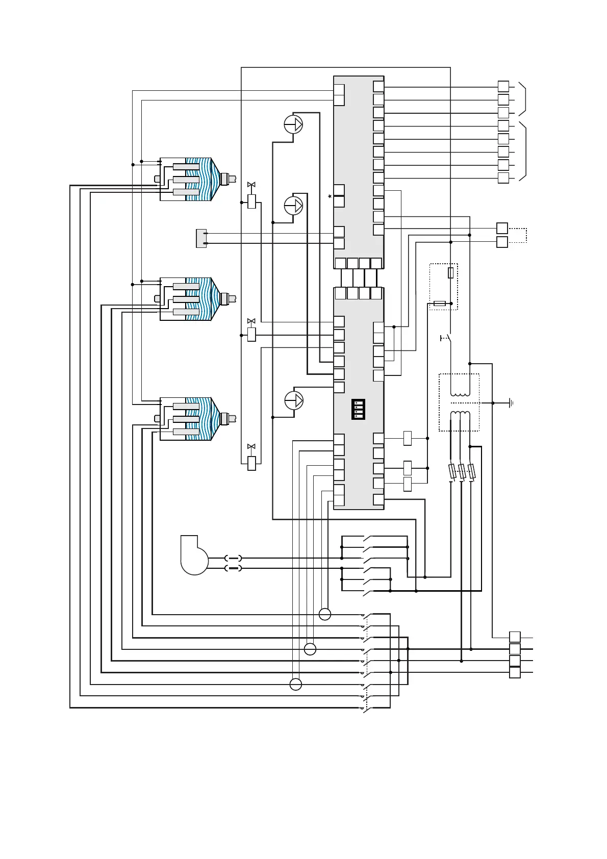
Alimentazione trifase (SD 3B3) Three-phase power supply (SD 3B3)
TAM 2
TAM 3
Drain pump 3
External signal Alarm
= Primary voltage
B = 200 - 208V~
C = 220 - 240V~
D = 380 - 415V~
E = 440 - 480V~
F = 575V~
***
Line
F2 2A ATM/gG
F3 4A ATM/gG
F1 4A ATM/gG
230V
0V
***
24V
0V
F5 4A GT
Transformer 630 VA
ON/OFF
X1
X2
56 57 58 59 60 70 71 72
Optional fan
K3
Conductimeter
L1 L2 L3 PE
Boiler 2
52 53 67 66
50 51
Control CDC / P / H / D / T
+12 S1 S2 GND -12 N0 C NC
65
64
55
54
G G0
68 69 61 62 56 57 58 59 60 70 71 72
12A
11A
10A
9A
8A 7A 6A 5A 4A 3A 4B 3B 2B 9C 8C 7C
1B 1C 2C 4C 3C 13A 5C 1A 6C 2A
Drain
Fill
GND
I sig
65
64
10A
9A
Drain Fill
Boiler 3
K1 K2 K3
Drain pump 1
Fill valve 1
Fill valve 3
Mounted on transformer
K2
K1
Boiler 1
Drain pump 2
TAM 1
K2 K3K3K1 K2K1
74
F4 2A GT
Fill valve 2
20 21
Remote On/Off
AD80000000
ON
OFF
1 2 3 4
* I morsetti 66-67 sono presenti solo sul controllo in versione CDD per gestire la deumidificazione (vedi pag. 20). Il controllo
CDD può essere abbinato al controllo Macrobase per la gestione dell'umidificazione e deumidificazione di centrali
di trattamento aria. Caratteristiche uscita 66-67: I max 5 mA, V max 30 V~
The connections 66-67 are present only on the CDD controller for the dehumidifier management (see on page 20). The
CDD controller can be coupled with the Macrobase controller for the humidification/dehumidification management of air
handling units. Output 66-67 characteristics: Imax 5mA; Vmax 30V~
See page 24-25