11
ENG
“humiSonic ventilation” +0300063EN - rel. 1.0 - 16.02.2016
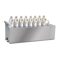
2. Attach the pipes to the quick couplings (C) to connect the fi ll/drain
valves;
C
1
2
Insert
Extract
Fig. 2.d
3. Reposition the cover, paying attention to the point of attachment (D).
D
Fig. 2.e
2.5 Feedwater
To ensure correct operation, humiSonic requires the use of demineralised
water, with the chemical and physical characteristics specifi ed in the table.
To ensure these water quality values, a reverse-osmosis demineralisation
system is typically used.
FEEDWATER
Quick coupling OD 8 mm (0,32”)
Temperature limits °C (°F) 1…40 (33.8 to 104)
Pressure limits MPa (bar) 0,1…0,6 (1 to 6)
Specifi c conductivity at 20°C 20…80 µS/cm
Total hardness 0…25 mg/l CaCO
3
Temporary hardness 0…15 mg/l CaCO
3
Total quantity of dissolved solids (cR) Depending on specifi c conductivity
(1)
Dry residue at 180°C Depending on specifi c conductivity
(1)
Iron + manganese 0 mg/l Fe+Mn
Chlorides 0 to 10 ppm Cl
Silicon dioxide 0 to 1 mg/l SiO2
Chlorine ions 0 mg/l Cl
Calcium sulphate mg/l CaSO4
Instant fl ow-rate (l/min) 2
Tab. 2.a
(1) = in general C
R
=0,65 * σ
R,20 °C
; R
180
= 0,93 * σ
R,20 °C
To avoid excessive oversizing of the reverse osmosis system, it is
recommended to avoid sizing the system based on instant fl ow-rate.
Rather, an expansion vessel should be installed between the water
treatment system and humiSonic.
The sizing calculations need to consider discontinuous water
consumption, comprising the following stages:
• fi lling (fi ll valve open);
• production (fi ll valve closed);
• washing (fi ll valve open).
The table below suggests the minimum sizes for connection to a generic
reverse osmosis system.
Model Storage Total expansion vessel volume
(pre-charge 1.5 bars)
Reverse osmosis
system
UU02 2.8 l 11.2 l 5.2 l/h
UU05 3.6 l 14.4 l 8.4 l/h
UU07 4.4 l 17.6 l 11.6 l/h
UU09 5.2 l 20.8 l 14.8 l/h
UU14 6.8 l 27.2 l 20.8 l/h
UU18 8.0 l 32.0 l 26.0 l/h
Tab. 0.a
If no storage vessel is available, the reverse osmosis system must
guarantee the instant fl ow-rate of the fi ll SV, equal to 2 l/min.
Connecting humiSonic to the Carel WTS Compact
The Carel product range includes a series of reverse osmosis systems
(“WTS Compact”) designed to produce water according to the feedwater
specifi cations and optimise connection to and operation with humiSonic
(see manuals +0300017 and +0300019).
All WTS Compact systems (P/N ROC%) always come with an expansion
vessel that maintains the required pressure in the circuit downstream.
Operation of the system is managed by pressure switches in the outlet
circuit. The basic rule for connection to the humidifi er is that the water
contained in the expansion vessel must be suffi cient to satisfy initial fi lling
and, if necessary, the washing cycle, while the WTS production time must
cover humiSonic production demand and fi ll the vessel as quickly as
possible.
The table below suggests the water consumption values and connections
for all sizes of humidifi ers.
Model Prod.
(l/h)
Tank
capacity (l)
Wash (l)
(*)
WTS Additional
vessel
UU02 2.4 0.8 4.8 ROC025500N Not required
UU05 4.8 1.6 5.6 ROC025500N Not required
UU07 7.2 2.4 6.4 ROC025500N Not required
UU09 9.6 3.2 7.2 ROC025500N Not required
UU14 14.4 4.8 8.8 ROC025500N ROKC00KTVE
UU18 18 6.0 10.0 ROC025500N ROKC00KTVE
Tab. 2.b
(*) Water consumption during the washing cycle is calculated based on
the default settings (1 wash every 24 hours, lasting 2 minutes, which ends
by totalling fi lling and emptying the volume of the tank). Consumption
depends on the fi ll solenoid valve fl ow-rate, which is 2 litres/minute. The
duration and frequency of the washing cycles are parameters that can be
set by the user, and these have a signifi cant impact on the sizing of the
WTS system.
Important:
1. do not add disinfectants or anticorrosive compounds to the water, as
these are potential irritants;
2. the use of well water, industrial water or water from cooling
circuits and, in general, any potentially chemically or bacteriologically
contaminated water is prohibited.
2.6 Drain water
This is not toxic and can be drained into the sewerage system, as defi ned
by directive 91/271/EEC on urban waste-water treatment.
DRAIN WATER
Quick coupling OD 8 mm (0,32”)
Typical temperature °C (°F) 1 to 40 (33.8 to 104)
Tab. 2.c
 Loading...


