Important:
• before proceeding with the electrical connections, ensure that the
control panel – humidifi er system is disconnected from the mains
power supply;
• make sure that the power supply voltage of the control panel
corresponds to the value indicated in the rated data.
To power up the humidifi er, connect the cables running from the
electrical panel:
1. +48 Vdc/ -48 Vdc from the power supply;
2. +24 Vac/ -24 Vac from the transformer;
3. the power cable for the lights (“Slave” electrical panel only);
4. the cable for the signal lights (“Slave” electrical panel) or RS485 serial
line (“Master” electrical panel).
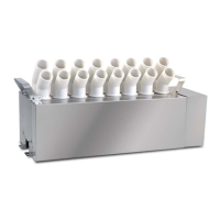
After having removed the screws (A), remove the side cover (B) and run
the cables through the cable glands on the case and inside the unit
(C). Then make the electrical connections (D) and reposition the cover,
repeating the same operations in reverse.
+ 48 V
- 48 V
G
G0
0TX/RX
+TX/RX
-TX/RX
+5V
WHITE
RED
ONOFF
COM
AL_A
AL_B
SHD
PE
Alarm contact (N.O.)
ON/OFF production
RED AND BLU LEDS
RS485
24 Vac Power Supply
48 Vdc Power Supply
Shield
A
B
C
D
Fig. 3.a
Note: to avoid unwanted interference, power cables should be kept
separate from probe signal cables.
DIPSWITCH CONFIGURATION
The dipswitches are located on the humidifi er control board. These must
be set before starting the humidifi er.
2
3
64
7
5
1
8
ON
Fig. 3.b
Key
1
Communication
OFF: Carel/Modbus Serial 485
ON: Reserved
2-3 Reserved
4
Serial 485 / tLAN baud rate
OFF: 19200
ON: 9600
5-6 Reserved
7 Reserved
8
Transducer production management
OFF: --> parallel
ON: --> series
 Loading...


