9
ENG
“humiSonic ventilation” +0300063EN - rel. 1.0 - 16.02.2016
1.11 Accessories
• BMS/RS485 serial card (P/N PCOS004850): to be installed on the control
board on the ““Master”” panel, used for direct interface to an RS485
network, with a maximum baud rate of 19200. The board guarantees
opto-isolation of the controller from the RS485 serial network.
• Humidity/temperature probes for ducts, CAREL P/Ns DPD*(T/H),
DPP*(T/H). Used in ducted heating and air-conditioning systems.
Supplied together with a mounting bracket. See manual +030220660.
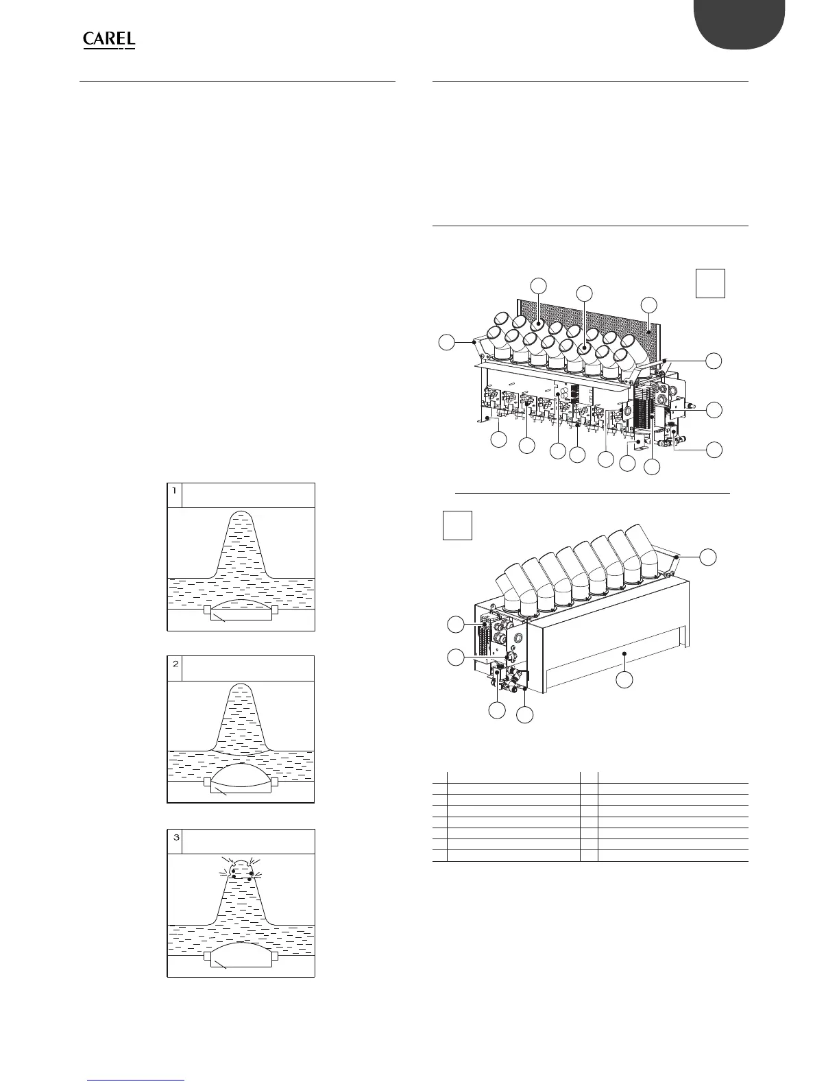
1.12 Structure
The fi gure shows the body of the humidifi er, once having removed the
side panels and the cover (see chap. “Spare parts and maintenance”).
F
2
5
12
3
6
11
4
7
10
5
7
1
1
1
8
9
6
8
13
8
R
Fig. 1.i
Key
F Front 7 Terminal block
R Rear 8 Fastening bracket
1 Lifting handles 9 Bracket with cable glands
2 Rear diff user 10 Piezoelectric transducer
3 Front diff user 11 Electronic control board
4 Baffl e 12 Driver
5 Fill valve 13 Air intake
6 Drain valve
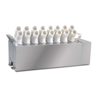
1.10 Operating principle
The operation of humiSonic humidifi ers is based on the principle of
atomisation of demineralised water using ultrasound technology. The
humidifi er operating principle can be summarised as follows:
• water fi ll via a fi ll solenoid valve until reaching the required level,
measured by the fl oat;
• if the autotest is enabled (default), the drain solenoid valve opens and
empties the tank (function designed to clean the tank of any residues/
dirt);
• water fi lled again to the required level;
• start ultrasonic atomisation (the air fl ow in the duct carries the particles
of moisture and distributes them into the surrounding environment);
• water refi ll based on the fl oat measures that the level has fallen below
the recommended value.
Ultrasound technology uses a voltage input signal that is transformed
via an oscillating circuit into a high frequency signal (1.7 MHz). This signal
supplies a transducer, the top of which is in contact with the water, which
starts vibrating at high frequency. The surface of the transducer vibrates
at very high speed (1.7 million times a second), a speed that does not
allow the water to move, due to its inertial mass. Consequently, a column
of water is created above the transducer. During the negative amplitude
of the transducer cycle, a void is created that is not fi lled by the water (as
this cannot respond to the extremely fast movements of the transducer).
The cavity thus created leads to the production of bubbles that are
pushed to the edge of the water column during the positive amplitude
of the cycle, thus colliding. During this process, very fi ne particles of water
are atomised on the edge of the water column. The resulting intersecting
sound waves created directly underneath the surface of the water cause
very small droplets of water to separate, forming a fi ne mist of vapour
that is immediately absorbed by the fl ow of air.
Dopo l'accensione
After switching on
Trasduttore / Transducer
Ampiezza negativa
Negative amplitude
Vuoto / Vacum
Trasduttore / Transducer
Ampiezza positiva
Positive amplitude
Trasduttore / Transducer
Fig. 1.h