8
ENG
“humiSonic ventilation” +0300063EN - rel. 1.0 - 16.02.2016
1
2
4
5
V: 1.5 - 3 m/s
3
basic panel
complete panel
6
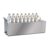
Fig. 1.c
Key
1 Stainless steel duct 4 Air fl ow
2 Humidifi er 5 Condensate collection basin
3 Control panel (external) 6 Drain trap
Important:
1. Choose the installation position so that the air fl ow disperses the
atomised water uniformly;
2. Make sure that the supporting surface is able to support the weight
of the unit.
The humidifi er can only be activated (atomised water production)
when the air handling unit fan is running. NEVER start atomised water
production without air fl ow in the duct: this may damage one or more
parts of the appliance.
1.7 Assembly
The appliance must be assembled on a horizontal support. Check correct
positioning using a spirit level.
Procedure:
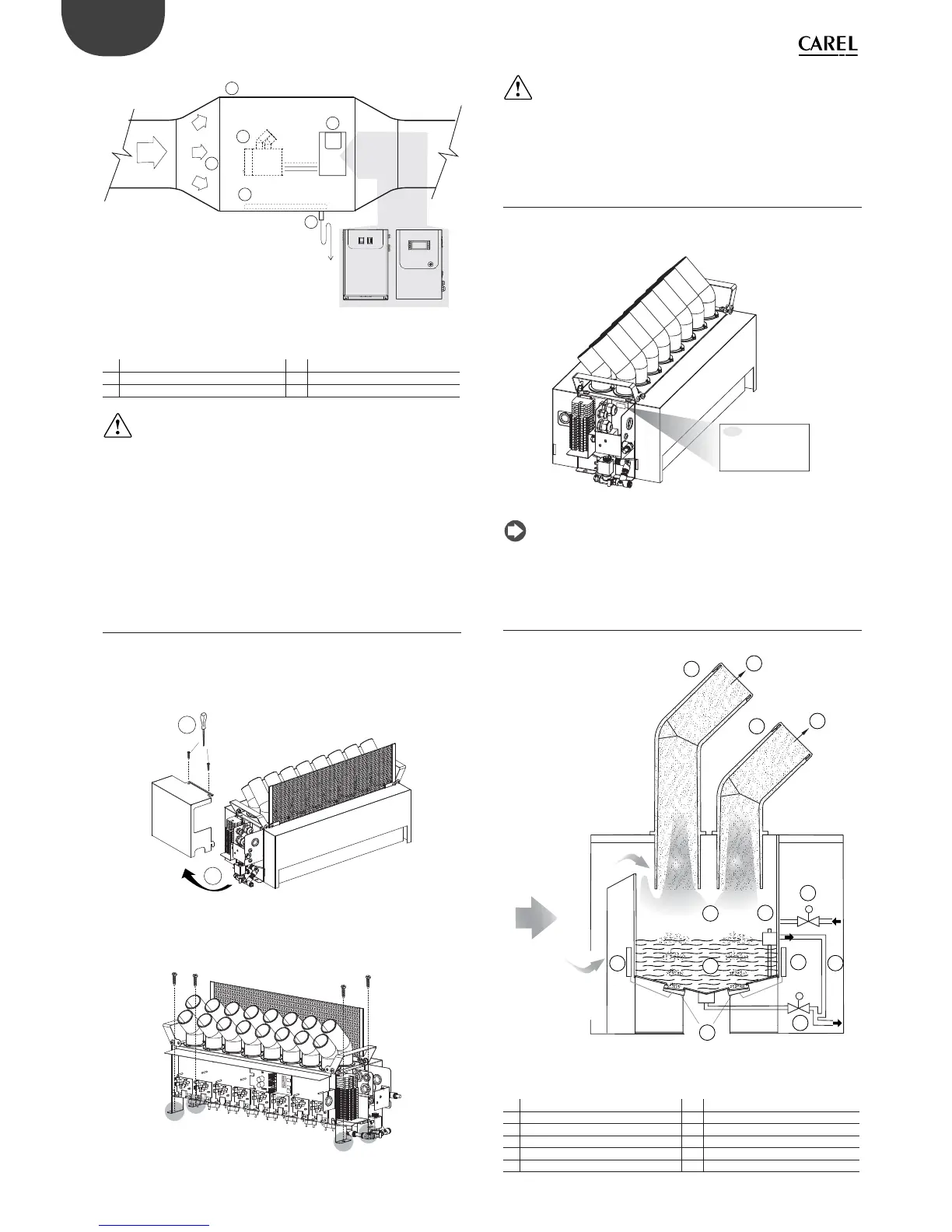
1. Unscrew the screws (A) and remove the right side cover (B);
A
B
Fig. 1.d
2. Secure the humidifi er to the horizontal support using the fastening
brackets on the right and left sides;
Fig. 1.e
Important:
1. Install the humidifi er in horizontal position, using a spirit level, so
that the level sensor does not give a false reading;
2. Carefully secure the unit so that it does not move during operation.
1.8 Identifi cation label
The humidifi ers are identifi able from the packaging label and the
identifi cation label on the side.
S.N.
A0002066 Rev.2.0
Date
Code
D
a
t
e
0
4
-
N
o
v
-
2
0
1
4
S
.
N.
A
0
0
0
2
0
6
6
R
e
v
.
C
o
d
e
UU1%D%0000
04-Nov-2014
Fig. 1.f
Note: tampering with, removing or failing to reattach the identifi cation
labels or anything else that prevents certain identifi cation of the product will
make installation and maintenance operations more diffi cult.
1.9 Functional diagram
M
M
1
1
2
2
3
4
6
5
7
8
9
9
10
air
flow
Fig. 1.g
Key
1 Atomised water 7 Float level sensor
2 Diff user 8 Tank
3 Atomisation chamber 9 Driver
4 Fill valve 10 Piezoelectric transducer
5 Overfl ow pipe 11 Power supply
6 Drain valve