36
ENG
“humiSonic ventilation” +0300063EN - rel. 1.0 - 16.02.2016
10.3 System information
This screen shows the currently installed software revision, the memory
usage and the cycle time.
Screen index Display description
Gb01 Information
FLSTDMHUSU
Version
Date Software release date
Bios BIOS release date
Boot BOOT release date
Gb02 Information
Board type
Board size
Total fl ash
RAM
Built-in type
Main cycle
Gb03 Firmware release
HW Id
Functional test
Tab. 10.c
10.4 Maintenance
Important: before performing any operations:
• power the unit off at the switch (off ) on the control panel;
• empty the water from the tank.
The fi ll valve is normally closed and the drain valve is normally open,
consequently, when powering down the humidifi er, the unit is drained
automatically.
Note: preventive maintenance on the humidifi er is recommended
to ensure optimum system performance. Maintenance includes:
• checking tightness of the electrical connectors;
• cleaning and visual inspection of the components;
• checking water level and making sure there are no leaks.
Important:
• the piezoelectric transducer is very delicate: when cleaning the inside
of the tank, make sure not to scratch it, for example with a screwdriver;
• tighten the nuts applying the maximum allowed torque (4 ± 0.5
kg·cm). Excessive tightening torque may damage the humidifi er.
10.5 Maintenance operations
Routine maintenance on humidifi ers operating on demineralised water
involves cleaning all the parts in contact with the water:
a. fi ll/drain lines;
b. water tank.
Special maintenance and repairs involve replacement of:
a. fi ll/drain solenoid valve;
b. driver board;
c. piezoelectric transducer;
d. electronic control board.
10.6 Maintenance intervals
Maintenance intervals depend on water quality and the quantity
of atomised water produced. An operating hour counter (eff ective
production) and a unit operating hour counter (total hours) can be set,
together with a maintenance hour counter, after which the display shows
a warning message. See alarm CL.
Screen
index
Display description Def Min Max UOM
Gc01 Hour counter
Work counter 0 0 32767 h
Machine counter 0 0 32767 h
Gc02 Hour counter
Maintenance hours 5000 0 20000 h
Reminder every 60 0 240 min
Tab. 10.d
Mains water
Water hardness 15…25 °f
(150 …250 μS/cm)
25…40 °f
(250 to 400 μS/cm)
Daily operating hours 8…10 8…10
Maintenance operations/year 2 3
Tab. 10.e
Demineralised water
The use of demineralised water minimises maintenance requirements.
Note: it is recommended to perform special maintenance and
repairs at least once a year, irrespective of the number of operating hours
shown on the operating hour counter.
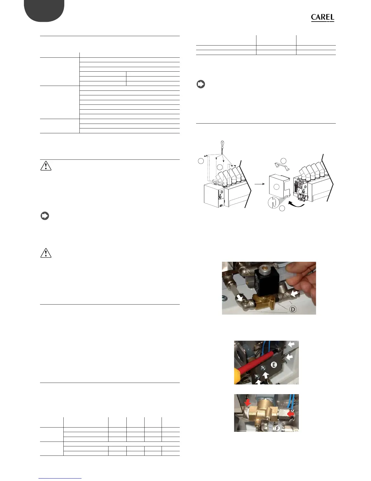
10.7 Replacing the components
Drain solenoid valve
To remove the right side cover:
V
A
C
B
M
Fig. 10.c
1. loosen and remove the screws (A) and release the cover (C) at point (B)
to remove. If necessary, loosen the screws (V) to remove the lifting
handle (M);
2. unplug the electrical connectors and move the spring fasteners so as to
remove the hoses, then remove the block (D): elbow connector, drain
valve, T-connector.
Fig. 10.d
Fill solenoid valve
1. loosen and remove the screws (arrows) so as to remove the bracket (E);
Fig. 10.e
Fig. 10.f
2. unplug the electrical connectors and move the spring fasteners so
as to remove the hoses, then remove the block (F): elbow connector,
fi ll valve, connector.