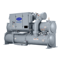
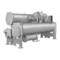
Fig. 18 — Cooler/Discharge Pipe Assembly Removal (Unit with P Compressor Shown)
1—Discharge Pipe
2—Tubesheet Mounting Bracket (Inside, Both Ends)
(Unbolt)
3—Cooler Liquid Feed Line (Cut)
4—Motor Drain Line (Unbolt)
5—Motor Cooling Line (Cut)
6—Economizer Line to Compressor (Option) (Cut)
7—Oil Supply
8—Vaporizer Vent Line (Cut)
9—Motor Cooling Line
10 — Oil Reclaim Line (Cut)
11 — Hot Gas Bypass Line (Cut)
12 — Compressor Discharge Temperature
13 — Compressor Discharge Pressure
14 — Compressor Discharge High Pressure Switch
15 — Discharge Pipe Relief Valve (Option or Accessory)
FRONT VIEW
BACK VIEW

 Loading...


