4
Identifying Drive by Part Number
— The VFD drive can
be identified by its part number (Fig. 9). This number appears
on the shipping label and on VFD nameplate.
Drive Input Component Location
— Figure 10 identifies the
control center components for the LiquiFlo 2.0 (LF-2) VFD.
Figure 11 identifies the control center components for the Std
Tier VFD.
Identifying Power Module by ID Number
— Each LF-2 AC
power module can be identified by its ID number. See Fig. 9.
This number appears on the shipping label and on the power
module’s nameplate. Power ratings for LF-2 VFDs are provided
in Table 1. Power ratings for Std Tier VFDs are provided in Ta-
ble 2.
INSTALLATION REQUIREMENTS — Certain installa-
tion requirements should be checked before continuing with
the chiller’s electrical installation. Input power wire sizes,
branch circuit protection, and control wiring are all areas that
need to be evaluated.
Determining Wire Size Requirements
— Wire size should be
determined based on the size of the conduit openings, and
applicable local, national, and international codes (e.g., NEC
[National Electric Code]/CEC [California Energy Commis-
sion] regulations). General recommendations are included in
the Carrier field wiring drawing.
Conduit Entry Size
— It is important to determine the size of
the conduit openings in the enclosure power entry plate so that
the wire planned for a specific entry point will fit through the
opening. Do NOT punch holes or drill into the top surface of
the control center enclosure for field wiring. Knockouts are
provided in the back of the control center for field control wir-
ing connections.
Recommended Control and Signal Wire Sizes
— The rec-
ommended minimum size wire to connect I/O signals to the
control terminal blocks is 18 AWG (American Wire Gage).
Recommended terminal tightening torque is 7 to 9 in.-lb
(0.79 to 1.02 N-m).
Recommended Airflow Clearances
— Be sure there is ade-
quate clearance for air circulation around the enclosure.
A 6-in. (152.4 mm) minimum clearance is required wherever
vents are located in the VFD enclosure.
Match Power Module Input and Supply Power Ratings
— It
is important to verify that building power will meet the input
power requirements of the Machine Electrical Data nameplate
input power rating. Be sure the input power to the chiller
corresponds to the chiller’s nameplate voltage, current, and
frequency. Refer to machine nameplate in Fig. 12. The
machine electrical data nameplate is located on the right side of
the control center.
PROVIDE MACHINE PROTECTION — Protect machine
and VFD enclosure from construction dirt and moisture. Keep
protective shipping covers in place until machine is ready for
installation.
If machine is exposed to freezing temperatures after water
circuits have been installed, open waterbox drains and remove
all water from cooler and condenser. Leave drains open until
system is filled.
It is important to properly plan before installing a 23XRV
unit to ensure that the environment and operating conditions
are satisfactory. The installation must comply with all require-
ments in the certified prints.
Chiller should be installed in an indoor environment where
the ambient temperature is between 40 and 104 F (4 and 40 C)
with relative humidity of 95% or less.
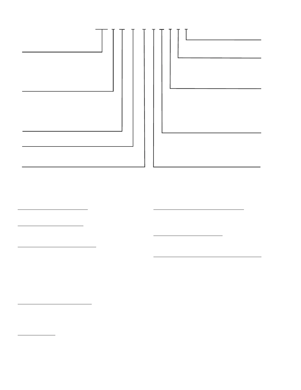
23XRV – High Efficiency
Variable Speed Screw Chiller
Cooler Size*
A1-A6
B1-B6
30-32
35-37
40-42
45-47
50-52
55-57
Condenser Size*
A1-A6
B1-B6
30-32
35-37
40-42
45-47
50-52
55-57
Economizer Option
E – With Economizer
N – No Economizer
Voltage Code
3 – 380-3-60
4 – 416-3-60
5 – 460-3-60
7 – 575-3-60 (Q and R compressors only)
9 – 380/415-3-50
S – Special
Compressor Option
0 – Full Load Optimized
1 – Part Load Optimized
Drive Code**
AA – LF-2, 440 Amps In, 442 Amps Out
BA – LF-2, 520 Amps In, 442 Amps Out
CC – LF-2, 608 Amps In, 608 Amps Out
EC – Std Tier, 575-v, 389 Amps In, 389 Amps Out
EF
– Std Tier, 575-v, 469 Amps In, 469 Amps Out
R2
– Std Tier, 230 Amps In, 230 Amps Out
R3
– Std Tier, 335 Amps In, 335 Amps Out
R4
– Std Tier, 445 Amps In, 445 Amps Out
23XRV 40 42 N R V AA 5 0
S
Compressor Code†
P
Q
R
Motor Code
H
J
P
Q
R
X
S
T
U
V
Fig. 2 — Model Number Identification
* First character denotes frame size.
† Only H and J motors are used with P compressors. Only type V
motors are used with Q compressors.
**Maximum limits only. Additional application limits apply that may
reduce these ampacities.
1016

 Loading...

