141
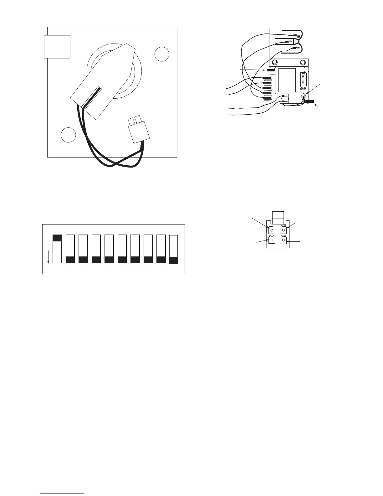
2. Review the DIP switch settings on the CoreSense mod-
ule. DIP switch no. 1 should be ON (up position) and all
other DIP switches should be OFF (down position). See
Fig. 163.
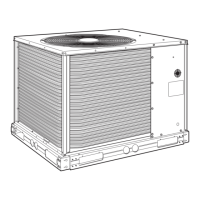
3. Install the CoreSense module in the compressor terminal
box as shown in Fig. 164, with the tabs holding the
module in place. Route the thermistor wire harness as
shown and plug the harness into the 2x2 socket on the
CoreSense module.
4. Connect the previously labeled M1, M2, T1, and T2
wires to the appropriate terminals on the CoreSense mod-
ule.
5. Connect the L1, L2, and L3 phase sensing wires to the
L1, L2, and L3 compressor terminal block connections.
See the compressor terminal cover diagram for identica-
tion of the L1, L2, and L3 terminal block connections.
6. Double-check the installation and make sure all connec-
tions are secure. Install the compressor terminal cover.
The CoreSense retrofit is complete and the system can be
put back into service.
CoreSense Communications Module Troubleshooting —
Copeland models with a "TE" in the electrical code (i.e.,
ZP182KCETED) have a motor overload system that consists
of an external CoreSense communication electronic control
module.
Motor thermistors are connected to the CoreSense commu-
nication module via a 2x2 plug (Fig. 165).
The CoreSense communications module has field configurable
DIP switches for addressing and configuring the module. The
DIP switches should be addressed as shown in Table 63.
The CoreSense communication module has a green and a
red light-emitting diode (LED). A solid green LED indicates
the module is powered and operation is normal. A solid red
LED indicates an internal problem with the module. If a solid
red LED is encountered, power down the module (interrupt the
T1-T2 power) for 30 seconds to reboot the module. If a solid
red LED is persistent, change the CoreSense module.
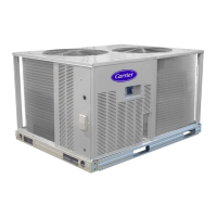
INSTALL IN THIS
ORIENTATION
A38-7311
Fig. 162 — Compressor Motor Sensor Harness
Installation
ROCKER DOWN
O
F
F
ON
OFF OFF OFF OFF OFF OFF OFF
OFF
123456789
OFF
10
A38-7812
Fig. 163 — CoreSense Communication DIP
Switch Settings for Kriwan Retrofit
1 2 3 4 5 6 7 8 9 10
T2 T1
L3
L2L1
RED
BLACK
WHITE
BLUE
HOLDING
TA B
HOLDING
TA B
THERMISTOR WIRE
HARNESS PLUGGED
INTO 2X2 SOCKET
BLACK
WHITE
A38-7313
Fig. 164 — CoreSense Communication Module
Mounting
MOTOR
PTC
CIRCUIT
SCROLL
NTC CIRCUIT
(NOT USED)
FOR FUTURE
USE
COMMON
CONNECTION
a38-7308
Fig. 165 — CoreSense Communications
Motor Thermistor Plug
 Loading...