EasyManuals Logo

Carrier SmartVu control User Manual

Carrier SmartVu control
168 pages
To Next Page IconTo Next Page
To Previous Page IconTo Previous Page
Page #97 background imageLoading...
Page #97 background image
SRDC-UG-2-14-000
REVISION
DATE
PAGE
19 Series Carrier®
SmartVu
TM
Controls IOM
2.3
Dec 4, 2020
97 OF 168
97
Step 3: Controller will reboot automatically to save the configuration
Note
Enable Modbus TCP, the Ethernet port will be used as Modbus / TCP interface, otherwise J8 port is
Modbus / RTU; if BACnet / IP is enabled, the Ethernet port 0 will be used as BACnet / IP interface,
otherwise J8 port is BACnet / mstp port.
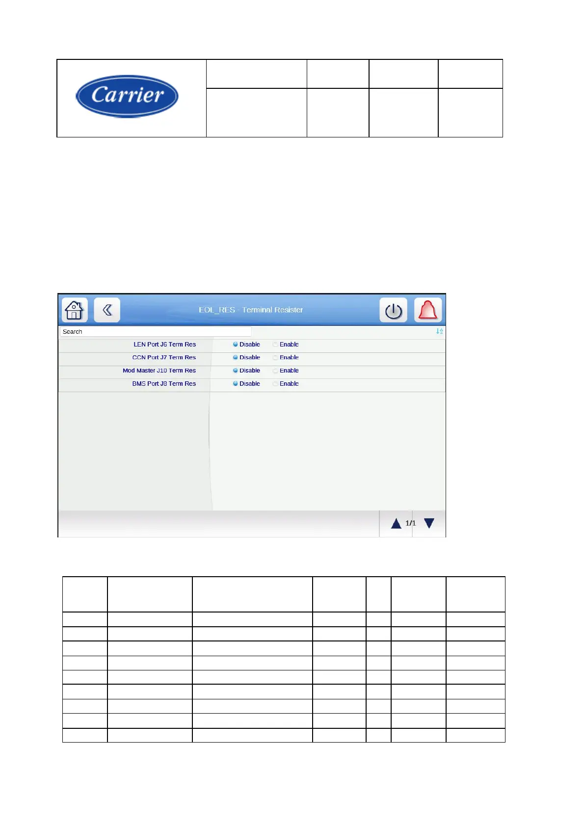
The PIC6 has the capability for field enabled termination on the RS485 ports. The function is enabled
through software. The termination resistance is 120 ohms.
Modbus R/W points information as following
ITEM
TagName
EnglishName
Description
Data
type
R/W
Modbus
address
M ode
1
ecdw_sp
Heating ECDW Setpoint
Analog
R/W
3000
Both
2
ecw_sp
Cooling ECW Setpoint
Analog
R/W
3002
Both
3
ice_sp
Ice Build Setpoint
Analog
R/W
3004
Both
4
lcdw_sp
Heating LCDW Setpoint
Analog
R/W
3006
Both
5
lcw_sp
Cooling LCW Setpoint
Analog
R/W
3008
Both
6
dem_base
Base Demand Limit
Analog
R/W
3010
Network
7
EWT_OPT
EWT Control Option
Switch
R/W
3012
Network
8
CHIL_S_S
Network:Cmd Start/Stop
Switch
R/W
3014
Network
9
CTRL_PNT
Control Point
Analog
R/W
3016
Network

Table of Contents

Questions and Answers:

Question and Answer IconNeed help?

Do you have a question about the Carrier SmartVu control and is the answer not in the manual?

Carrier SmartVu control Specifications

General IconGeneral
BrandCarrier
ModelSmartVu control
CategoryControl Panel
LanguageEnglish

Related product manuals