`
5
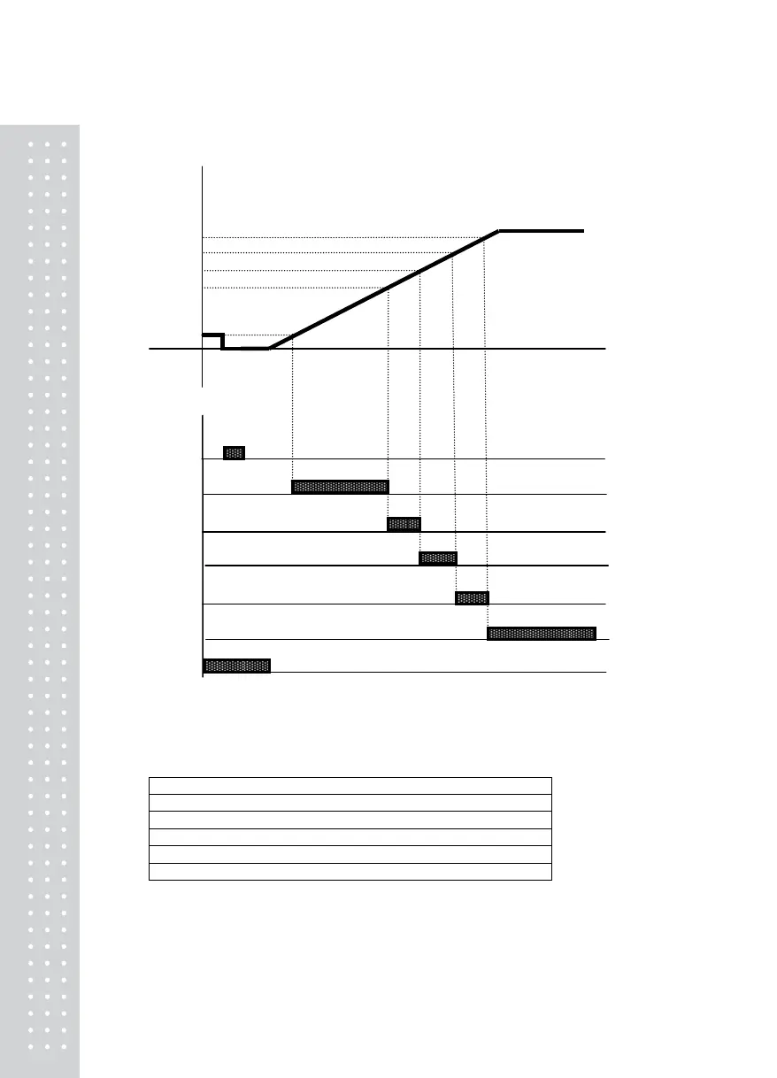
<Checker Mode 3> Relay Operation Graph when #7 of F51 is Set
Weight
Above Step4
Step4
ST
Step3
Step2
Step1
Near Zero
Tare External Input
Near Zero ≤Step1(SP1) Output1
Step1(SP1)≤ Step2(SP2) Output2
Step2(SP2)≤ Step3(SP3) Output3
Step3(SP3)≤ Step4(SP4) Output4
Above Step4(SP4) Output5
Near Zero Output6
Note.
1. Required set value input: Step4(SP4) > Step3(SP3) > Step2(SP2) > Step1(SP1)
2. Near zero output is according to the specified range in F57.
3. Each output relay will output if it reaches the set value or is within the range
4. Relay Output
SP1: Output(operated) in between Near Zero and Step 1
SP2: Output(operated) in between Step 1 and Step 2
SP3: Output(operated) in between Step 2 and Step 3
SP4: Output(operated) in between Step 3 and Step 4
Above SP4: Output(operated) when over Step 4 value
Near Zero: F57 Set Value ≥ 0 Range Output
5. Step1`-4(SP 1-4)‘s status lamp in the front panel is operated in the same manner as the RELAY output.



 To Next Page