`
67
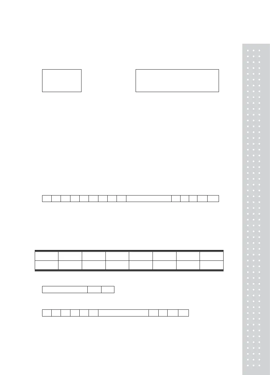
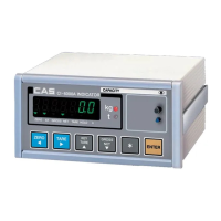
② Remote Display Connection (CD-SERIES)
Connect the C/L Port on the back side of the Indicator to the 2 PIN connector of the
Remote display as shown below:
C/L1 ㅇ
--------------------------
ㅇ 1 Receive Data
C/L2 ㅇ
--------------------------
ㅇ 2 Signal Ground
C/L Terminal 2 PIN Connector (Female)
Indicator’s C/L Port 2 PIN Connector of the Remote Display
2) Data format
① Communication Rate: 1,200 bps – 115,200 bps
(Set at the F23 set value)
② Data bit: 8, Stop bit: 1, Parity bit: None
Data bit: 7, Stop bit: 1, Parity bit: Even #/odd #
(Set at F21 Parity Bit set value)
③ Code : ASCII
④ When data is sent to computer?
(Set at F22 Communication Data Set-up)
⑤ Transmission Data Format (set at F24 output format)
* 22 byte of CAS
. . .
DATA (8byte
)
CR LF
└─┘ └──┘ │ └──────┐ │ └──┘
US(Unstable) GS(GROSS weight) Device ID Lamp condition byte Empty Unit (kg/t)
ST(Stable) NT(NET weight)
OL(Overload)
- Device ID : Transmit 1 byte so that the receiver can receive data selectively which indicator
sent.(Device ID is selected in F23 .)
- Byte for Status Lamp
Bit 7 Bit 6 Bit 5 Bit 4 Bit 3 Bit 2 Bit 1 Bit 0
1 Stable 1 Hold Print Net Tare Zero
* 10 byte of CAS
DATA (8byte
)
CR LF
* 18 byte of AND
. .
DATA (8byte
)
CR LF
└─┘ └──┘ └──┘
US(Unstable) GS(GROSS weight) Unit (kg/t)
ST(Stable) NT(NET weight)
OL(Overload)