— 34 —
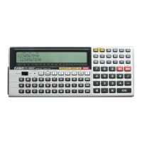
Charger
AC Adaptor
RBATCHG (to Detector)
VBAT2 (to Detector)
VDETDRB (Normally H)
To V3 and V5 circuits.
RBATMAIN (to Detector)
Fuse
FS1
Q53
Q54
D15
Alkaline
(1.6 ~ 3.4 V)
NiMH
(1.9 ~ 2.8 V)
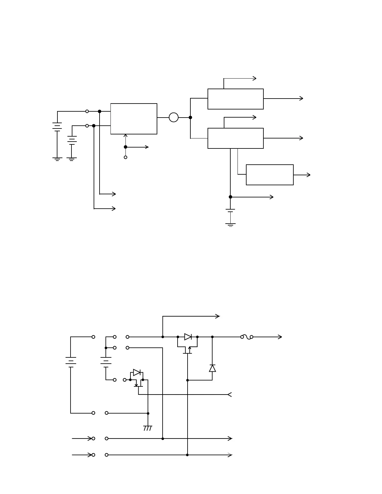
POWER SUPPLY CIRCUIT
The power supply circuit consists of 4 blocks which are Primary circuit, 5 V circuit, 3 V circuit and 25 V
circuit as follows;
Alkaline
NiMH
Fuse
5 V system
3 V system
25 V system
AC Adaptor
Primary
circuit
To Primary Detector (VBAT2)
To Primary Detector (RBATCHG)
To Detector (VSUB)
To Secondary Detector (V5MAIN)
To Secondary Detector (V3MAIN)
Lithium
To Detector (RBATMAIN)
Primary Circuit
The voltage from both batteries, alkaline and NiMH, supplies to V5 and V3 circuits through the fuse when
the battery is loaded.
The VBAT2 and RBATCHG are for the reference voltage for Primary detectors. VBAT2 is for alkaline
batteries detector. RBATCHG is for NiMH detector.
RBATMAIN is for AC adaptor detector. It detects whether AC adaptor is used or not.
VDETDRB is to prevent overdischarge of NiMH. When the unit turns off automatically caused by low bat-
tery of NiMH, VDETDRB from detector is H. Then Q54 turns off, it makes the GND line for NiMH cut.
3 V circuit
5 V circuit
25 V circuit